Service Manuals, User Guides, Schematic Diagrams or docs for : . Car Manuals Toyota Camry 1994.2002-2007 Approved Toyota Camry 2007 Hybrid 50 bodypane front0
<< Back | HomeMost service manuals and schematics are PDF files, so You will need Adobre Acrobat Reader to view : Acrobat Download Some of the files are DjVu format. Readers and resources available here : DjVu Resources
For the compressed files, most common are zip and rar. Please, extract files with Your favorite compression software ( WinZip, WinRAR ... ) before viewing. If a document has multiple parts, You should download all, before extracting.
Good luck. Repair on Your own risk. Make sure You know what You are doing.
Image preview - the first page of the document
>> Download front0 documenatation <<
Text preview - extract from the document
BP-12                                   BODY PANEL REPLACEMENT


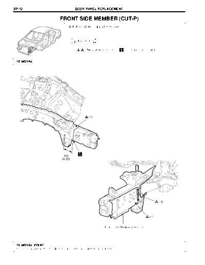
                            FRONT SIDE MEMBER (CUT-P)
                                  With the radiator support removed.


                                       Symbol meaning


                                              : Remove Weld Points       : Cut and Join Location

                        F25712A                                                                         F25712B

 REMOVAL


                               110
                              (4.33)


                                                           Front Side Member Extension

                                                                                                   mm (in.)
                                                                                                         F25712

 REMOVAL POINT
 1  Remove the front side member extension at the same time.
                                         BODY PANEL REPLACEMENT                                                 BP-13


   Symbol meaning

       : MIG Plug Weld          : Butt Weld

                                                                                                                F25713B

INSTALLATION


                                                                       Front Side Member Extension

                                                                                                                 F25713

INSTALLATION POINT
1   Temporarily install the new parts and measure each part of the new parts in accordance with the body
    dimension diagram. (See the body dimension diagram)
2   After welding, apply undercoating to the corresponding parts. (See the paint.coating)
3   After applying the top coat, apply anti-rust agent to the internal panel portion of the closed section structural
    weld points.
◦ Jabse Service Manual Search 2026 ◦ Jabse Pravopis ◦ onTap.bg ◦ Other service manual resources online : Fixya ◦ eServiceinfo