Service Manuals, User Guides, Schematic Diagrams or docs for : . Car Manuals Toyota Camry 1994.2002-2007 Approved Toyota Camry 2007 Hybrid 50 bodypane front1
<< Back | HomeMost service manuals and schematics are PDF files, so You will need Adobre Acrobat Reader to view : Acrobat Download Some of the files are DjVu format. Readers and resources available here : DjVu Resources
For the compressed files, most common are zip and rar. Please, extract files with Your favorite compression software ( WinZip, WinRAR ... ) before viewing. If a document has multiple parts, You should download all, before extracting.
Good luck. Repair on Your own risk. Make sure You know what You are doing.
Image preview - the first page of the document
>> Download front1 documenatation <<
Text preview - extract from the document
                         BODY PANEL REPLACEMENT                                          BP-19


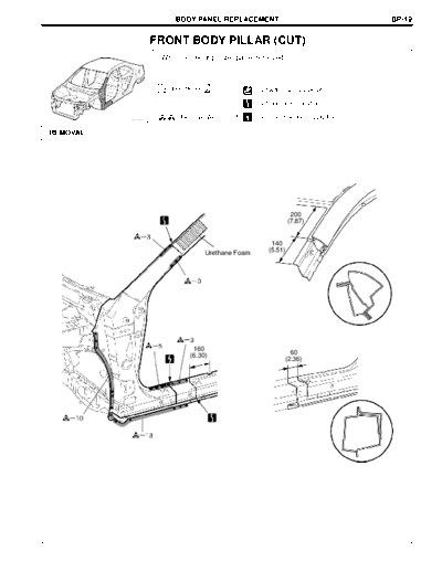
                    FRONT BODY PILLAR (CUT)
                     With the cowl top outer panel removed.


                     Symbol meaning               : Cut with disc sander, etc.

                                                  : Cut and Join Location

                         : Remove Weld Points     : Cut Location for Supply Parts
          F25722A                                                                        F25722B

REMOVAL


                                                                 200
                                                                (7.87)


                                                        140
                                  Urethane Foam        (5.51)


                              160
                             (6.30)                            60
                                                             (2.36)


                                                                                    mm (in.)
                                                                                          F25722
BP-20                                BODY PANEL REPLACEMENT


   Symbol meaning              : Cut with disc sander, etc.

                               : Cut and Join Location

        : Remove Weld Points   : Cut Location for Supply Parts
                                                                 F25722B


                                                                  F25723
                                           BODY PANEL REPLACEMENT                                                BP-21


   Symbol meaning
           : MIG Plug Weld         : Cut and Join Location

         : Tack Weld         : Butt Weld       : Body Sealer
                                                                                                                 F25724B

INSTALLATION


 Cowl Side Panel


                         45
                       (1.77)


                                                                            Center Body Pillar Lower Reinforce
                                                                 310
                                                               (12.20)


                                    Front Body Pillar Lower Reinforce


                                                     20
                                                   (0.79)


                                                                                                            mm (in.)
                                                                                                                  F25724

INSTALLATION POINT
1   Before temporarily installing the new parts, weld the center body pillar lower reinforce, front body pillar lower
    reinforce and cowl side panel with the standard number of welding points.
BP-22                                          BODY PANEL REPLACEMENT


    Symbol meaning

            : MIG Plug Weld         : Cut and Join Location

          : Tack Weld         : Butt Weld        : Body Sealer
                                                                                                                        F25724B


                                       Front Body Pillar
                                       Lower Reinforce


                                                                   Cowl Side Panel


                                            Center Body Pillar
                                            Lower Reinforce


                                                                                        10
                                                                                      (0.39)


                                                                                                                   mm (in.)
                                                                                                                         F25725

 INSTALLATION POINT
 1   Inspect the fitting of the related parts around the new parts before welding. This affects the appearance of the finish.
 2   Temporarily install the new parts and measure each part of the new parts in accordance with the body
     dimension diagram. (See the body dimension diagram)
 3   After welding the center body pillar lower reinforce, front body pillar lower reinforce and cowl side panel to the
     vehicle side, install the front body upper outer pillar and center body outer pillar.
                                           BODY PANEL REPLACEMENT                                                       BP-23


  Front Body Upper Outer Pillar


                                                           Urethane Foam


                                                                Center Body Outer Pillar


                                                                                           No. 6 Pillar Outer Bracket


                                     Center Body Pillar
                                     Lower Reinforce


                                                                                                                        F25807

INSTALLATION POINT
1   Inspect the fitting of the related parts around the new parts before welding. This affects the appearance of the finish.
2   Temporarily install the new parts and measure each part of the new parts in accordance with the body
    dimension diagram. (See the body dimension diagram)
3   Before installing a new part, apply body sealer.
    HINT:
    1) Apply sealer in an even, continuous bead.
4   After welding the center body pillar lower reinforce and front body pillar lower reinforce to the vehicle side,
    install the front body upper outer pillar, center body outer pillar and No.6 pillar outer bracket.
5   After welding, apply the polyurethane foam to the corresponding parts. (See the paint.coating)
6   After welding, apply body sealer and undercoating to the corresponding parts. (See the paint.coating)
7   After applying the top coat, apply anti-rust agent to the internal panel portion of the closed section structural
    weld points.
◦ Jabse Service Manual Search 2026 ◦ Jabse Pravopis ◦ onTap.bg ◦ Other service manual resources online : Fixya ◦ eServiceinfo