Service Manuals, User Guides, Schematic Diagrams or docs for : . Car Manuals Toyota Celica 1988-1989.1993-1994.2000 Approved Toyota Celica 1989 steering column switches
<< Back | HomeMost service manuals and schematics are PDF files, so You will need Adobre Acrobat Reader to view : Acrobat Download Some of the files are DjVu format. Readers and resources available here : DjVu Resources
For the compressed files, most common are zip and rar. Please, extract files with Your favorite compression software ( WinZip, WinRAR ... ) before viewing. If a document has multiple parts, You should download all, before extracting.
Good luck. Repair on Your own risk. Make sure You know what You are doing.
Image preview - the first page of the document

>> Download steering column switches documenatation <<
Text preview - extract from the document
                                 STEERING COLUMN SWITCHES

                                       1988 Toyota Celica


          1988 STEERING
          Toyota - Steering Wheel & Column Switches

          All Models

    REMOVAL & INSTALLATION

    * PLEASE READ THIS FIRST *
CAUTION: When performing work on vehicles equipped with Supplemental
         Restraint System (SRS), exercise extreme caution when working
         around steering wheel or column. DO NOT apply electrical
         power to any component on steering column without
         disconnecting SRS control unit (air bag system may be
         activated).

    STEERING WHEEL & HORN
         Removal
         1) Disconnect battery ground cable. Remove screws attaching
horn button assembly/center pad to steering wheel from behind steering
wheel (if equipped).


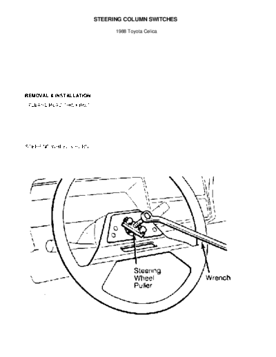
Fig. 1:   Removing Steering Wheel

         2) Pull horn button assembly/center pad from steering wheel.
Use a cloth covered screwdriver to pry off horn button assembly/center
pad (if necessary). Disassemble horn button assembly (if necessary).
         3) Place springs, contacts, horn or cruise control harness
connectors and screws in order for reassembly reference. Place wheels
in a straight-ahead position.


Fig. 2:   Exploded View of Typical Steering Wheel Assembly

         4) Remove steering wheel retaining nut and washer. Mark
steering wheel and shaft for reassembly reference. Using a steering
wheel puller, remove steering wheel. See Fig. 1.
         5) Place steering wheel, cruise control set/resume switch
(if equipped), canceling cams, springs and slip rings in order for
reassembly reference.

         Installation
         1) Coat slip ring contact surfaces with a light electrical
grease. Assemble horn button assembly (if disassembled). Ensure wheels
are in a straight-ahead position.
         2) Aligning marks made during removal, place slip ring,
springs, canceling cams, steering wheel, washer and steering wheel
retaining nut on shaft.
         3) Tighten nut to specification. See
STEERING WHEEL TORQUE SPECIFICATIONS table at the end of this article.
To complete reassembly, reverse removal procedure.

    COMBINATION SWITCH
         Removal
         Remove steering wheel. Remove upper and lower steering
column covers. Disconnect combination switch harness connectors.
remove snap ring and washer from steering shaft (if equipped). Remove
combination switch attaching screws. Remove combination switch.

         Installation
         To install, reverse removal procedure. Ensure all electrical
connections are tight. Check canceling operation of turn signal
switch.

    STEERING LOCK & IGNITION SWITCH
         Removal
         1) Remove steering wheel, upper and lower steering column
covers and combination switch. Disconnect ignition switch harness
connectors.
         2) If the shear bolt studs are accessible, use a hacksaw to
cut a slot into the exposed studs. Using a screwdriver, remove the
studs.
         3) If the shear bolt studs are recessed or hard to reach with
a hacksaw, center punch studs. Using a drill bit and a screw
extractor, remove studs. Remove steering lock and ignition switch.

         Installation
         1) To install, reverse removal procedure. Install new shear
bolts. Tighten shear bolts finger tight. Ensure proper operation of
steering lock and ignition switch.
         2) Tighten shear bolts until heads break off. Install
combination switch, upper and lower steering column covers and
steering wheel.

        TORQUE SPECIFICATIONS
STEERING WHEEL TORQUE SPECIFICATIONS TABLE
◦ Jabse Service Manual Search 2024 ◦ Jabse Pravopis ◦ onTap.bg ◦ Other service manual resources online : Fixya ◦ eServiceinfo