Service Manuals, User Guides, Schematic Diagrams or docs for : . Car Manuals Toyota Celica 1988-1989.1993-1994.2000 Approved Toyota Celica 1994 K sensor range charts
<< Back | HomeMost service manuals and schematics are PDF files, so You will need Adobre Acrobat Reader to view : Acrobat Download Some of the files are DjVu format. Readers and resources available here : DjVu Resources
For the compressed files, most common are zip and rar. Please, extract files with Your favorite compression software ( WinZip, WinRAR ... ) before viewing. If a document has multiple parts, You should download all, before extracting.
Good luck. Repair on Your own risk. Make sure You know what You are doing.
Image preview - the first page of the document
>> Download K sensor range charts documenatation <<
Text preview - extract from the document
                               K - SENSOR RANGE CHARTS

                                      1994 Toyota Celica


         1994 ENGINE PERFORMANCE
         Toyota Sensor Operating Range Charts

         Celica

    INTRODUCTION
         Sensor operating range information can help determine if a
sensor is out of calibration. An out-of-calibration sensor may not set
a trouble code, but it may cause driveability problems.

NOTE:   Unless stated otherwise in testing procedure, perform all
        voltage tests using a Digital Volt-Ohmmeter (DVOM) with a
        minimum 10-megohm input impedance.

    INTAKE AIR TEMPERATURE SENSOR
NOTE:   Intake air temperature sensor may be also identified using
        appropriate illustration in E - THEORY/OPERATION article.

         1) Ensure ignition is off. Disconnect electrical connector
from intake air temperature sensor. Intake air temperature sensor is
located in air intake, near air filter.
         2) Remove intake air temperature sensor. Place threaded end
of intake air temperature sensor and thermometer in container of
water. Attach ohmmeter between intake air temperature sensor
electrical terminals.
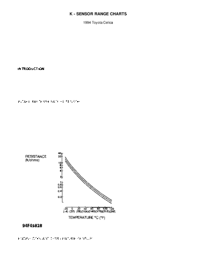
         3) Heat water and note that resistance is within
specification in relation to temperature. See Fig. 1. Replace intake
air temperature sensor if defective.


Fig. 1: Checking Intake Air Temperature Sensor
Courtesy of Toyota Motor Sales, U.S.A., Inc.

    ENGINE COOLANT TEMPERATURE SENSOR
         Measure coolant temperature sensor resistance between sensor
terminals. For resistance specifications, see Fig. 2.


Fig. 2: Checking Engine Coolant Temperature Sensor
Courtesy of Toyota Motor Sales, U.S.A., Inc.

        EGR GAS TEMPERATURE SENSOR
EGR GAS TEMPERATURE SENSOR SPECIFICATIONS TABLE (1)
◦ Jabse Service Manual Search 2026 ◦ Jabse Pravopis ◦ onTap.bg ◦ Other service manual resources online : Fixya ◦ eServiceinfo