Service Manuals, User Guides, Schematic Diagrams or docs for : . Car Manuals Toyota Celica 1988-1989.1993-1994.2000 Approved Toyota Celica 1994 anti lock brake system
<< Back | HomeMost service manuals and schematics are PDF files, so You will need Adobre Acrobat Reader to view : Acrobat Download Some of the files are DjVu format. Readers and resources available here : DjVu Resources
For the compressed files, most common are zip and rar. Please, extract files with Your favorite compression software ( WinZip, WinRAR ... ) before viewing. If a document has multiple parts, You should download all, before extracting.
Good luck. Repair on Your own risk. Make sure You know what You are doing.
Image preview - the first page of the document
>> Download anti lock brake system documenatation <<
Text preview - extract from the document
                                 ANTI-LOCK BRAKE SYSTEM

                                           1994 Toyota Celica


           1994 BRAKES
           Toyota Anti-Lock Brake System

           Celica

    DESCRIPTION
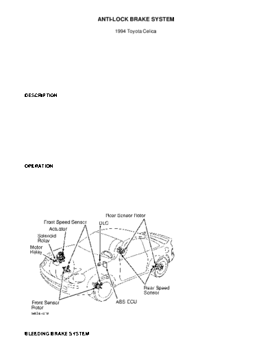
         Anti-Lock Brake System (ABS) consists of an ABS Electronic
Control Unit (ECU), solenoid relay, motor relay, actuator and 4 speed
sensors. See Fig. 1.
         An ABS indicator light is located on the instrument panel.
This light comes on for 3 seconds as a bulb test when ignition is
first turned on. A primary check is performed after each engine start,
and initial vehicle speed exceeds 4 MPH. If brake pedal is pressed
before vehicle exceeds 4 MPH, primary check will not occur until brake
pedal is released.

NOTE:      For more information on brake system, see appropriate
           BRAKE SYSTEM article.

    OPERATION
          Under normal driving conditions, ABS functions as a standard
brake system. With detection of wheel lock-up, short pedal pulsations
occurring in rapid succession will be felt in brake pedal. Pedal
pulsation will continue until there is no longer a need for ABS
function.

CAUTION:   See ANTI-LOCK BRAKE SAFETY PRECAUTIONS article in GENERAL
           INFORMATION.


Fig. 1: Locating ABS Components
Courtesy of Toyota Motor Sales, U.S.A., Inc.

    BLEEDING BRAKE SYSTEM
CAUTION:   Brake fluid will damage painted surfaces. If brake fluid
           gets on a painted surface, wipe off immediately and clean
           with alcohol. Use only DOT 3 brake fluid from a sealed
           container. Do not mix brake fluid with any other type.

         Brake bleeding procedure is same procedure used to bleed non-
ABS systems. If master cylinder was rebuilt or reservoir ran empty,
bleed master cylinder first. Bleed remaining wheels, starting with
brake having longest hydraulic line, working to brake with shortest
hydraulic line.

    ADJUSTMENTS

    MASTER CYLINDER PUSH ROD
         1) Install Adjusting Gauge (09737-00010) onto master
cylinder, with master cylinder gasket in place. Lower gauge pin until
it just touches master cylinder piston. See Fig. 2 (STEP 1). Invert
gauge, then install onto power brake unit (STEP 2).
         2) Measure clearance between brake unit push rod and head of
adjusting gauge. Clearance should be zero. If clearance is not zero,
adjust brake unit push rod length until push rod just touches head of
gauge pin.


Fig. 2: Adjusting Master Cylinder Push Rod
Courtesy of Toyota Motor Sales, U.S.A., Inc.

    BRAKE PEDAL HEIGHT
          1) Measure brake pedal height from face of brake pedal pad to
asphalt sheet under carpet. See Fig. 3. Brake pedal height should be
6.0-6.4" (152-162 mm). To adjust brake pedal height, remove instrument
lower finish panel and air duct (if necessary). Unplug stoplight
switch connector. Loosen stoplight switch and lock nut on brake pedal
push rod.
          2) Adjust pedal height by rotating push rod. After adjusting
brake pedal height, tighten lock nut. Adjust stoplight switch. See
STOPLIGHT SWITCH. Check and adjust brake pedal free play. See BRAKE
PEDAL FREE PLAY.


Fig. 3: Measuring Brake Pedal Height & Free Play
Courtesy of Toyota Motor Sales, U.S.A., Inc.

    BRAKE PEDAL FREE PLAY
         1) Brake pedal free play is distance brake pedal travels
(with engine stopped) before encountering resistance. To measure brake
pedal free play, press brake pedal several times to exhaust vacuum
from power brake unit. Press brake pedal and measure travel until
initial resistance occurs.
         2) Brake pedal free play should be .04-.24" (1-6 mm). If free
play is not within specification, adjust by rotating push rod. See
Fig. 3. After adjusting brake pedal free play, check brake pedal
height. See BRAKE PEDAL HEIGHT.

    BRAKE PEDAL RESERVE DISTANCE
         Measure brake pedal reserve distance from face of brake pedal
pad to asphalt sheet under carpet, with engine running and force of
110 lbs. (50 kg) applied to brake pedal. Minimum brake pedal reserve
distance should be 3.35" (85 mm) for vehicles with 1.8L engine, or 3.
54" (90.0 mm) for vehicles with 2.2L engine. If distance is less than
specified, inspect brake system.

    STOPLIGHT SWITCH
         Stoplight switch is located above brake pedal. See Fig. 3. To
adjust stoplight switch, loosen stoplight switch lock nuts and rotate
stoplight switch until clearance between pedal stop and threaded end
of switch is .02-.09" (0.5-2.3 mm). Tighten lock nut. Check stoplight
operation.

    PARKING BRAKE SHOES (DISC)
         Raise and support vehicle. Remove wheels. Temporarily install
lug nuts to hold brake rotor in place. Remove hole plug to gain access
to adjuster. Turn adjuster to expand shoes until brake rotor locks.
Back off adjuster 8 notches. Install hole plug.

    PARKING BRAKE
NOTE:    Service brake on rear drum brakes and parking brake shoe
         clearance on rear disc brakes must be adjusted before
         adjusting parking brake cable.

         Parking brake lever stroke should be 4-7 clicks with a   pull
force of 44 lbs. (20 kg). To adjust stroke, remove console box.   Loosen
parking brake cable lock nut. Rotate adjuster nut until parking   brake
lever travel is as specified. Tighten lock nut. Install console   box.

    TROUBLE SHOOTING
         ABS Does Not Operate
         Verify that only normal   code exists. SEE RETRIEVING CODES
under DIAGNOSIS & TESTING. Check   IG1 power source. See IG1 POWER
SOURCE CIRCUIT under DIAGNOSIS &   TESTING. See WIRING DIAGRAM. Check
ABS actuator. See ACTUATOR CHECK   under DIAGNOSIS & TESTING.

         ABS Does Not Operate Efficiently
         Verify that only normal code exists. SEE RETRIEVING CODES
under DIAGNOSIS & TESTING. Check stoplight circuit. See WIRING
DIAGRAM. Check ABS actuator. See ACTUATOR CHECK under DIAGNOSIS &
TESTING.

         ABS Warning Light Abnormal
         See ABS WARNING LIGHT CIRCUIT under DIAGNOSIS & TESTING.

         Cannot Retrieve Codes
         Check ABS warning light circuit. See ABS WARNING LIGHT
CIRCUIT under DIAGNOSIS & TESTING. Check Tc terminal circuit. See Tc
TERMINAL CIRCUIT under DIAGNOSIS & TESTING.

         Cannot Perform Sensor Signal Check
          Check Ts terminal circuit. See Ts TERMINAL CIRCUIT under
DIAGNOSIS & TESTING.

    DIAGNOSIS & TESTING
NOTE:    DO NOT start engine when retrieving diagnostic codes.

    RETRIEVING CODES
         1) Ensure battery voltage is about 12 volts. Turn ignition
on. ABS light should come on, then go out after 3 seconds. If warning
light does not come on, check fuse, bulb, and wiring harness.
          2) With ignition on, remove short pin from Data Link
Connector (DLC). See Fig. 4. Connect jumper wire between DLC terminals
Tc and E1. See Fig. 4. If a malfunction is detected, 4 seconds will
elapse, then ABS light will begin to flash a 2-digit code. First
series of flashes indicates first digit of code. After a 1.5-second
pause, second series of flashes indicates second digit of code.
         3) If 2 or more codes are stored, there will be a 2.5-second
pause between each code. After all codes are displayed, a 4-second
pause will occur, then all codes will repeat. If ABS system is
functioning properly, ABS light will flash 2 times every second. For
code interpretation, see DIAGNOSTIC CODES.
         4) After replacing or repairing malfunctioning components,
clear diagnostic codes. If a battery cable was disconnected during
repairs, all codes will be erased. If battery cable was not
disconnected during repairs, see CLEARING CODES.


Fig. 4: Identifying Data Link Connector (DLC) Terminals
Courtesy of Toyota Motor Sales, U.S.A., Inc.

    DIAGNOSTIC CODES
         Check suspect components in order given. Checks consist
mainly of a visual inspection and continuity tests.

         Code 11
         Open in solenoid relay circuit. Check actuator wiring
harness, solenoid relay, solenoid relay wiring harness and solenoid
relay connector. See SOLENOID RELAY under COMPONENT TESTING.

         Code 12
         Short in solenoid relay circuit. Check actuator wiring
harness, solenoid relay, solenoid relay wiring harness and solenoid
relay connector. See SOLENOID RELAY under COMPONENT TESTING.
         Code 13
         Open in pump motor relay circuit. Check actuator wiring
harness, pump motor relay, pump motor relay wiring harness and pump
motor relay connector. See MOTOR RELAY under COMPONENT TESTING.

         Code 14
         Short in pump motor relay circuit. Check actuator wiring
harness, pump motor relay, pump motor relay wiring harness and pump
motor relay connector. See MOTOR RELAY under COMPONENT TESTING.

         Code 21
         Open or short circuit in solenoid for right front wheel.
Check actuator solenoid, wiring harness and connector. See ACTUATOR
CHECK under DIAGNOSIS & TESTING. See ABS ACTUATOR under COMPONENT
TESTING.

         Code 22
         Open or short circuit in solenoid for left front wheel. Check
actuator solenoid, wiring harness and connector. See ACTUATOR CHECK
under DIAGNOSIS & TESTING. See ABS ACTUATOR under COMPONENT TESTING.

         Code 23
         Open or short circuit in solenoid for right rear wheel. Check
actuator solenoid, wiring harness and connector. See ACTUATOR CHECK
under DIAGNOSIS & TESTING. See ABS ACTUATOR under COMPONENT TESTING.

         Code 24
         Open or short circuit in solenoid for left rear wheel. Check
actuator solenoid, wiring harness and connector. See ACTUATOR CHECK
under DIAGNOSIS & TESTING. See ABS ACTUATOR under COMPONENT TESTING.

         Code 31
         Malfunction of right front wheel speed sensor signal. Check
speed sensor, sensor rotor, wiring harness and connector. See SPEED
SENSOR DIAGNOSTICS under DIAGNOSIS & TESTING. See FRONT SPEED SENSORS
under COMPONENT TESTING.

         Code 32
         Malfunction of left front wheel speed sensor signal. Check
speed sensor, sensor rotor, wiring harness and connector. See SPEED
SENSOR DIAGNOSTICS under DIAGNOSIS & TESTING. See FRONT SPEED SENSORS
under COMPONENT TESTING.

         Code 33
         Malfunction of right rear wheel speed sensor signal. Check
speed sensor, sensor rotor, wiring harness and connector. See SPEED
SENSOR DIAGNOSTICS under DIAGNOSIS & TESTING. See REAR SPEED SENSORS
under COMPONENT TESTING.

         Code 34
         Malfunction of left rear wheel speed sensor signal. Check
speed sensor, sensor rotor, wiring harness, and connector. See SPEED
SENSOR DIAGNOSTICS under DIAGNOSIS & TESTING. See REAR SPEED SENSORS
under COMPONENT TESTING.

         Code 35
         Open in left front or right rear wheel speed sensor circuit.
Check speed sensor, sensor rotor, wiring harness and connector. See
SPEED SENSOR DIAGNOSTICS under DIAGNOSIS & TESTING. See appropriate
speed sensor testing under COMPONENT TESTING.

        Code 36
        Open in right front or left rear wheel speed sensor circuit.
Check speed sensor, sensor rotor, wiring harness and connector. See
SPEED SENSOR DIAGNOSTICS under DIAGNOSIS & TESTING. See appropriate
speed sensor testing under COMPONENT TESTING.

          Code 37
          Rear speed sensor rotor malfunction. Check rear sensor
rotors.

         Code 41
         Battery voltage is less than 9.5 volts or more than 16.2
volts. Check battery and voltage regulator.

         Code 51
         Actuator pump motor is locked or pump motor circuit open.
Check pump motor, pump motor relay, vehicle battery, actuator wiring
harness, connectors, actuator pump motor circuit and actuator ground
bolt. See ACTUATOR CHECK under DIAGNOSIS & TESTING. See MOTOR RELAY
under COMPONENT TESTING.

         ABS Light Always On
         Malfunction of ABS ECU. Inspect ABS ECU connector for proper
installation and undamaged terminals. Repair as necessary. If
connector is okay, temporarily substitute known good ABS ECU. Retest
system.

    CLEARING CODES
         Turn ignition on. Connect jumper wire between DLC terminals
Tc and E1. See Fig. 4. With vehicle stopped, press brake pedal 8 or
more times within 3 seconds. Codes will be erased. Verify ABS light
goes out after 3 seconds. Verify ABS light flashes a normal code. See
RETRIEVING CODES under DIAGNOSIS & TESTING.

    ABS WARNING LIGHT CIRCUIT
         1) If ABS warning light does not come on at all, go to step
2). If ABS warning light stays on, go to step 3).
         2) Check light bulb and associated wiring. If bulb and wiring
are okay, check solenoid relay. See SOLENOID RELAY under COMPONENT
TESTING. If relay is okay, check for open circuit in wiring between
DLC and solenoid relay, or poor ground connection.
         3) Remove short pin from DLC. See Fig. 4. If ABS warning
light goes out, go to next step. If warning light remains on, check
for short circuit in wiring between DLC and ABS ECU.
         4) Check solenoid relay. See SOLENOID RELAY under COMPONENT
TESTING. If relay is okay, check for short in wiring between DLC and
solenoid relay.

    ACTUATOR CHECK
         1) Ensure battery voltage exists. Turn ignition off. Unplug
actuator electrical connectors. Connect Test Harness (09990-00200) and
Actuator Checker (09990-00150) to vehicle according to manufacturer's
instructions.
         2) Place Sheet "A" (09990-00163) onto actuator checker. Start
and idle engine. Set selector switch to FRONT RH position. Press and
hold MOTOR switch for a few seconds. Press and hold brake pedal for
about 15 seconds. Pedal should not go down. As brake pedal is held,
press MOTOR switch for a few seconds. Brake pedal should not pulsate.

NOTE:     DO NOT press POWER switch for longer than 10 seconds.

          3) Press and hold brake pedal. Push and hold POWER switch for
a few seconds. When POWER switch is pressed, brake pedal should not go
down. Release POWER switch. Brake pedal should go down. Press and hold
MOTOR switch for a few seconds. Brake pedal should return. Release
MOTOR switch. Release brake pedal.
         4) Repeat steps 2) through 4) for FRONT LH, REAR RH, and REAR
LH by setting selector switch to appropriate positions. After checking
remaining wheels, press and hold MOTOR switch for a few seconds. Stop
engine. Remove test harnesses and actuator checker. Reconnect actuator
wiring to actuator. Clear diagnostic codes. See CLEARING CODES.

    IG1 POWER SOURCE CIRCUIT
         1) Ensure charging system is working properly. Repair as
necessary. Turn ignition on. Measure voltage between ABS ECU connector
terminals IG1 and GND. See Fig. 5. Battery voltage should exist. If
battery voltage does not exist, go to next step. If battery voltage
exists, replace ABS ECU.
         2) Check resistance between ABS ECU connector terminal GND
and body ground. Resistance should be one ohm or less. If resistance
is not as specified, repair or replace wiring harness or connector as
necessary. If resistance is as specified, check ECU-IG1 fuse, located
in fuse box.
         3) If fuse is okay, check for open in wiring harness and
connector between ABS ECU and battery. If fuse is not okay, check for
short in all wiring harness components connected to ECU-IG1 fuse. See
WIRING DIAGRAM.


Fig. 5: Identifying ABS ECU Connector Terminals
Courtesy of Toyota Motor Sales, U.S.A., Inc.

    Tc TERMINAL CIRCUIT
         Turn ignition on. Check for battery voltage between terminals
Tc and E1 of DLC. See Fig. 4. If battery voltage does not exist, check
for open or short circuit in associated wiring. See WIRING DIAGRAM. If
wiring is okay, temporarily substitute known good ABS ECU. Retest
system.

    Ts TERMINAL CIRCUIT
         Turn ignition on. Check for battery voltage between terminals
Ts and E1 of DLC. See Fig. 4. If battery voltage does not exist, check
for open or short circuit in wiring between DLC and ABS ECU, or
between DLC and ground. See WIRING DIAGRAM. If wiring is okay,
temporarily substitute known good ABS ECU. Retest system.
    SPEED SENSOR DIAGNOSTICS
NOTE:   While diagnosing speed sensors, system functions as a
        standard brake system.

         1) Ensure battery voltage is about 12 volts. Turn ignition
on. ABS light should come on, then go out after about 3 seconds. If
ABS light does not come on, check fuse, bulb, and wiring harness.
         2) Turn ignition off. DO NOT remove short pin from DLC.
Connect DLC terminals Ts and E1. See Fig. 4. Engage parking brake.
Start engine. Verify ABS light flashes 4 times per second.
         3) Drive vehicle straight ahead at speed greater than 28 MPH.
Stop vehicle. Connect jumper between DLC terminals Tc and E1.
See Fig. 4. If a malfunction is detected, 4 seconds will elapse, then
ABS light will begin to flash a 2-digit code. First series of flashes
indicates first digit of code. After a 1.5 second pause, second series
of flashes indicates second digit of code.
         4) If 2 or more codes are stored, there will be a 2.5-second
pause between each code. After all codes are flashed, there will be a
4-second pause, then all codes will repeat.
         5) Record diagnostic codes. Turn ignition off. Repair as
necessary. See SPEED SENSOR DIAGNOSTIC CODES. Remove jumper wires from
DLC. Clear diagnostic codes. See CLEARING CODES.

    SPEED SENSOR DIAGNOSTIC CODES
         Code 71
         Low voltage of right front speed sensor signal. Check right
front speed sensor and sensor installation.

         Code 72
         Low voltage of left front speed sensor signal. Check left
front speed sensor and sensor installation.

         Code 73
         Low voltage of right rear speed sensor signal. Check right
rear speed sensor and sensor installation.

         Code 74
         Low voltage of left rear speed sensor signal. Check left rear
speed sensor and sensor installation.

         Code 75
         Abnormal signal from right front speed sensor. Check right
front sensor rotor.

         Code 76
         Abnormal signal from left front speed sensor. Check left
front sensor rotor.

         Code 77
         Abnormal signal from right rear speed sensor. Check right
rear sensor rotor.

         Code 78
         Abnormal signal from left rear speed sensor. Check left rear
sensor rotor.

        ABS Light Blinks 4 Times A Second
        All speed sensors and sensor rotors are normal.

    COMPONENT TESTING
◦ Jabse Service Manual Search 2026 ◦ Jabse Pravopis ◦ onTap.bg ◦ Other service manual resources online : Fixya ◦ eServiceinfo