Service Manuals, User Guides, Schematic Diagrams or docs for : . Car Manuals Toyota Celica 1988-1989.1993-1994.2000 Approved Toyota Celica 1994 door locks power
<< Back | HomeMost service manuals and schematics are PDF files, so You will need Adobre Acrobat Reader to view : Acrobat Download Some of the files are DjVu format. Readers and resources available here : DjVu Resources
For the compressed files, most common are zip and rar. Please, extract files with Your favorite compression software ( WinZip, WinRAR ... ) before viewing. If a document has multiple parts, You should download all, before extracting.
Good luck. Repair on Your own risk. Make sure You know what You are doing.
Image preview - the first page of the document
>> Download door locks power documenatation <<
Text preview - extract from the document
                                 DOOR LOCKS - POWER

                                      1994 Toyota Celica


         1994 ACCESSORIES & EQUIPMENT
         Toyota Motor Sales, U.S.A., Inc. - Power Door Locks

         Celica

    DESCRIPTION & OPERATION
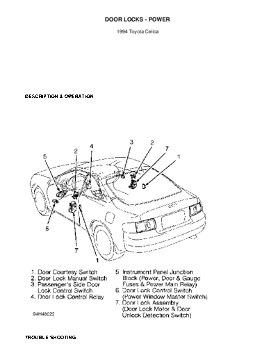
         All doors can be locked or unlocked simultaneously using
either front door. Turning driver-side door lock once will unlock
driver-side door only, twice will unlock all doors. Door locks can be
controlled by switches on driver-side or passenger-side doors within
vehicle, or by operating each door lock with key or lock knob. Front
door(s) cannot be manually locked when key is in ignition switch. See
Fig. 1.


Fig. 1: Locating Power Door Lock Components
Courtesy of Toyota Motor Sales, U.S.A., Inc.

    TROUBLE SHOOTING
NOTE:       Trouble shoot problems in the order listed.

            Door Lock System Does Not Operate

        *   Check   fuse(s).
        *   Check   door lock switch signal.
        *   Check   door lock motor operation.
        *   Check   door lock control relay. See POWER DOOR LOCK CONTROL
            RELAY   CIRCUIT TESTING CHARTS.
        *   Check   harness and connectors.

            Door Lock System Does Not Operate With Manual Switch

        *   Check   door lock manual switch.
        *   Check   door lock control relay. See POWER DOOR LOCK CONTROL
            RELAY   CIRCUIT TESTING CHARTS.
        *   Check   door lock motor operation.
        *   Check   harness and connectors.

            Door Lock System Does Not Operate With Door Key

        *   Check   door key lock and unlock switch
        *   Check   door lock control relay. See POWER DOOR LOCK CONTROL
            RELAY   CIRCUIT TESTING CHARTS.
        *   Check   harness and connectors.
        *   Check   door lock link disconnected.

            Driver Door 2-Key Turns, Key Unlock Function Does Not Operate

        *   Check   door key lock and unlock switch.
        *   Check   harness and connectors.
        *   Check   door lock control relay. See POWER DOOR LOCK CONTROL
            RELAY   CIRCUIT TESTING CHARTS.

            Key In Ignition Switch Warning, Does Not Operate

        *   Check   key unlock warning switch.
        *   Check   door courtesy switch.
        *   Check   door lock switch.
        *   Check   harness and connectors.
        *   Check   door lock control relay. See POWER DOOR LOCK CONTROL
            RELAY   CIRCUIT TESTING CHARTS.

            Only One Door Lock Does Not Operate

        *   Check door lock motor operation.
        *   Check harness and connectors.

    TESTING

    COMPONENT TESTING
NOTE:       For connector terminal identification, see WIRING DIAGRAM.

         Door Courtesy Switch
         Locate door courtesy switch in each door, next to power door
lock assembly. Ensure continuity exists between terminal(s) and switch
body with switch pin released (switch ON). Ensure no continuity exists
between terminal(s) and switch body with switch pin pushed in (switch
OFF). If continuity is not as specified, replace switch and retest
system.
         Door Key Lock & Unlock Switch
         Locate door key lock and unlock switch connector behind door
panel. Disconnect 7-pin connector. Ensure continuity exists between
switch terminals No. 2 and 3 with switch in LOCK position. Ensure
continuity exists between switch terminals No. 1 and 2 with switch in
UNLOCK position. If continuity is not as specified, replace switch and
retest system.

         Door Lock Manual Switch (Driver & Passenger Sides)
         Locate door lock manual switch in front door. Disconnect 4-
pin connector. Ensure continuity exists between switch terminals No. 2
(White/Black wire) and No. 4 (Blue/Black wire) with switch in LOCK
position. Ensure continuity exists between switch terminals No. 2 and
No. 3 (Blue wire) with switch in UNLOCK position. Ensure no continuity
exists in OFF position. If continuity is not as specified, replace
switch and retest system.

         Door Lock Motor Operation
         Locate front or rear door lock motor, and disconnect door
lock motor 7-pin connector. Connect positive battery lead to terminal
No. 7 (Blue/White wire) and negative battery lead to terminal No. 5
(Blue/Red wire). Ensure door lock link moves to LOCK position. Reverse
battery leads and ensure door lock link moves to UNLOCK position. If
door lock motor operation is not as specified, replace door lock
assembly and retest system.

         Door Unlock Detection Switch
         Locate front door lock motor and disconnect door lock motor
7-pin connector. Ensure continuity exists between connector terminals
No. 4 (Green wire) and No. 6 (White/Black wire) with door unlock
detection switch in UNLOCK position. Ensure no continuity exists with
switch in LOCK position. If continuity is not as specified, replace
door lock assembly and retest system.

         Key Unlock Warning Switch
         Locate ignition switch 10-pin connector. With key removed
from switch, ensure continuity exists between connector terminals No.
1 and 5. If continuity is not present, replace key unlock warning
switch.

         Positive Temperature Coefficient (PTC) Thermistor Operation
         1) Locate front or rear door lock motor in door. Disconnect
door lock motor 7-pin connector. Connect positive battery lead to door
lock motor terminal No. 7 (Blue/White wire). Connect ammeter positive
lead to door lock motor terminal No. 5 (Blue/Red wire) and ammeter
negative lead to negative battery terminal. Ensure current changes
from 3.2 amps to less than 0.5 amp within 20-70 seconds. If current
changes as specified, go to next step. If current does not change as
specified, replace door lock assembly.
         2) Disconnect test leads from terminals and wait at least 60
seconds. Connect positive battery lead to door lock motor terminal No.
5 and negative battery lead to terminal No. 7. Ensure door lock link
moves to LOCK position. If operation is not as specified, replace door
lock assembly and retest system.

    DOOR LOCK SWITCH SIGNAL TEST
NOTE:   Ensure power door lock harness and connector circuits are
        okay before testing door lock switch signal. See the
        POWER DOOR LOCK CONTROL RELAY CIRCUIT TESTING CHARTS.

         Door Lock Switch Signal
         Locate power door lock control relay. Ensure control relay
16-pin connector is connected. Using voltmeter positive lead,
backprobe Blue/Red wire terminal of connector. Using voltmeter
negative lead, backprobe Blue/White wire terminal of connector. Ensure
voltage increases from zero to battery voltage for approximately 0.2
second with door lock manual switch in UNLOCK position. Reverse
voltmeter leads and ensure voltage increases from zero to battery
voltage for approximately 0.2 second with door lock manual switch in
LOCK position. If voltage does not change as specified, replace power
door lock control relay and retest system.

    POWER DOOR LOCK CONTROL RELAY CIRCUIT TESTING CHARTS
NOTE:   Power door lock ECU or control relay circuit test charts are
        provided to pinpoint a malfunctioning circuit. Checking pin
        voltages at power door lock ECU or control relay connectors
        will help determine if power door lock ECU and control relay
        are receiving and sending proper voltage signals. Using test
        charts may also help determine if there is a short or open
        in harness or connectors.

NOTE:   Unless stated otherwise in testing procedures, perform all
        voltage tests using a Digital Volt-Ohmmeter (DVOM) with a
        minimum 10-megohm input impedance. Voltage readings may vary
        slightly due to battery condition or charging rate.


Fig. 2: Power Door Lock Control Relay Circuit Connector
Courtesy of Toyota Motor Sales, U.S.A., Inc.
Fig. 3: Power Door Lock Control Relay Circuit Testing
Courtesy of Toyota Motor Sales, U.S.A., Inc.

    WIRING DIAGRAM
Fig. 4:   Power Door Lock Wiring Diagram
◦ Jabse Service Manual Search 2026 ◦ Jabse Pravopis ◦ onTap.bg ◦ Other service manual resources online : Fixya ◦ eServiceinfo