Service Manuals, User Guides, Schematic Diagrams or docs for : . Car Manuals Toyota Celica 1988-1989.1993-1994.2000 Approved Toyota Celica 1994 fuses and circuit breakers
<< Back | HomeMost service manuals and schematics are PDF files, so You will need Adobre Acrobat Reader to view : Acrobat Download Some of the files are DjVu format. Readers and resources available here : DjVu Resources
For the compressed files, most common are zip and rar. Please, extract files with Your favorite compression software ( WinZip, WinRAR ... ) before viewing. If a document has multiple parts, You should download all, before extracting.
Good luck. Repair on Your own risk. Make sure You know what You are doing.
Image preview - the first page of the document
>> Download fuses and circuit breakers documenatation <<
Text preview - extract from the document
                               FUSES & CIRCUIT BREAKERS

                                       1994 Toyota Celica


          Fuses & Circuit Breakers
          1994-96 Toyota

          Celica

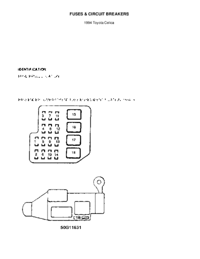
    IDENTIFICATION

    FUSE PANEL LOCATION
         There are 3 fuse panels on this vehicle. The driver's side
fuse box is located behind the driver's kick panel. The passenger's
side fuse box is behind the passenger's side kick panel. The main fuse
and relay block is in the engine compartment.

    PASSENGER COMPARTMENT FUSE BOXES IDENTIFICATION (1994-96)


Fig. 1: Passenger Compartment Fuse Identification (1994-96)
Courtesy of Toyota Motor Sales, U.S.A., Inc.

      *   1 - 15 Amp
          Automatic Transmission System, Anti-Lock Brake System
 *   2 - 20 Amp
     Not Used
 *   3 - 7.5 Amp
     Instrument Panel Lights
 *   4 - 15 Amp
     Stop Lights, High Mounted Stoplight, Fuel Injection System,
     Automatic Transmission System, Anti-Lock Brake System,
     Cruise Control System Cancel Device
 *   5 - 20 Amp
     Not Used
 *   6 - 15 Amp
     Cigarette Lighter & Digital Clock, Audio System
 *   7 - 7.5 Amp
     Charging System & Discharge Warning Light, Multiport Fuel
     Injection, SRS Airbag
 *   8 - 20 Amp
     Windshield Wipers/Washers, Rear Wiper/Washer
 *   9 - 10 Amp
     Fuel injection System
 *   10 - 10 Amp
     Turn Signal Lights, Hazard Flashers
 *   11 - 15 Amp
     Taillights, Parking Lights, Side Marker Lights, License
     Light
 *   12 - 10 Amp
     Air Conditioning System, Rear Window Defogger
 *   13 - 10 Amp
     Gauges & Meters, Power Door Lock System
 *   14 - 7.5 Amp
     Starting System, Fuel Injection System
 *   15 - 40 Amp
     Electronic Ignition System/Distributor Ignition System
 *   16 - 30 Amp
     Power Door Lock System
 *   17 - 30 Amp
     Rear Window Defogger
 *   18 - 30 Amp
     Power Windows, Electric Moonroof
 *   19 - 10 Amp
     Air Conditioning System

ENGINE COMPARTMENT MAIN FUSE IDENTIFICATION (1994-96)
Fig. 2: Engine Compartment Main Fuse ID (1994-96)
Courtesy of Toyota Motor Sales, U.S.A., Inc.

WARNING: Always disconnect battery ground cable before servicing
         "high-current fuses. It is recommended that "high-current"
     fuses be replaced by a qualified technician.

 *   1 - 30 Amp
     Headlight (Left Side)
 *   2 - 10 Amp
     Hazard Flashers
 *   3 - 7.5 Amp
     Horns
 *   4 - 20 Amp
     Car Audio System
 *   5 - 15 Amp
     Anti-Lock Brake System
 *   6 - 10 Amp
     Clock, Interior Lights, Door Courtesy Lights, Trunk Light,
     Luggage Compartment Light, Open Door Warning Light
 *   7 - 15 Amp
     Headlight (Left Side)
 *   8 - 15 Amp
     Headlight (Right Side)
 *   9 - Spare
 *   10 - Spare
 *   11 - Spare
 *   12 - 40 Amp
     Air Conditioning System
 *   13 - 30 Amp
     Cooling Fan
 *   14 - 30 Amp
     Condenser Cooling Fan
 *   15 - 100 Amp
     All Components in ALT-S, Tail, Door, Def and Power Circuits
 *   16 - 60 Amp
     All Components in Am2, Hazard, Horn, Dome and Radio Circuits
 *   17 - 50 Amp
     Anti-Lock Brake System
 *   18 - 7.5 Amp
     Charging System
 *   19 - 7.5 Amp
     SRS Airbag Warning Light
 *   20 - 15 Amp
     Electronic Fuel Injection System

ENGINE COMPARTMENT RELAY IDENTIFICATION (1994-96)
     To identify fuses, see Fig. 2.

 *   A   -   Fan No. 1
 *   B   -   Engine Main
 *   C   -   Headlight
 *   D   -   Horn
 *   E   -   Starter
 *   F   -   EFI Main
◦ Jabse Service Manual Search 2026 ◦ Jabse Pravopis ◦ onTap.bg ◦ Other service manual resources online : Fixya ◦ eServiceinfo