Service Manuals, User Guides, Schematic Diagrams or docs for : . Car Manuals Toyota Celica 1988-1989.1993-1994.2000 Approved Toyota Celica 1994 steering column standard
<< Back | HomeMost service manuals and schematics are PDF files, so You will need Adobre Acrobat Reader to view : Acrobat Download Some of the files are DjVu format. Readers and resources available here : DjVu Resources
For the compressed files, most common are zip and rar. Please, extract files with Your favorite compression software ( WinZip, WinRAR ... ) before viewing. If a document has multiple parts, You should download all, before extracting.
Good luck. Repair on Your own risk. Make sure You know what You are doing.
Image preview - the first page of the document
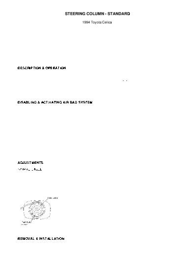
>> Download steering column standard documenatation <<
Text preview - extract from the document
                             STEERING COLUMN - STANDARD

                                      1994 Toyota Celica


         1994 STEERING
         Toyota - Steering Column - Standard

         Celica

    DESCRIPTION & OPERATION
         Steering column is a collapsible 2-piece design. Columns use
shear pins to absorb collision impact. Steering shaft is connected
directly to steering gear with either flexible coupling or "U" joint.
Some models have an air bag integral with the steering wheel pad.

NOTE:    For models with tilt wheel steering columns, see
         STEERING COLUMN - TILT article in STEERING section.

    DISABLING & ACTIVATING AIR BAG SYSTEM
WARNING: Before any repairs are performed on air bag equipped models,
         disconnect and shield negative battery cable. Wait at least
         90 seconds after disconnecting battery cable before
         performing any repairs. Air bag system retains enough voltage
         to deploy air bag for a short time after disconnecting power.
         Use caution when working around steering column. Air bag
         could deploy.

         To disable air bag system, ensure ignition switch is in LOCK
position and negative battery terminal is disconnected for at least 90
seconds before attempting any repair. DO NOT apply electrical power to
any component on steering column without disconnecting air bag control
unit. Information labels are attached to air bag components. Follow
all notices on labels. See the AIR BAG RESTRAINT SYSTEM article in the
ACCESSORIES/SAFETY EQUIPMENT section.

    ADJUSTMENTS

    SPIRAL CABLE
         On vehicles equipped with air bag system, spiral cable MUST
be correctly adjusted to ensure proper air bag operation. Ensure front
wheels are in straight-ahead position. Turn spiral cable (located on
combination switch) counterclockwise by hand until it becomes harder
to turn cable. Turn spiral cable clockwise about 3 turns and ensure
Red marks align and are visible through inspection hole. See Fig. 1.


Fig. 1: Adjusting Air Bag Spiral Cable
Courtesy of Toyota Motor Sales, U.S.A., Inc.

    REMOVAL & INSTALLATION
    STEERING WHEEL & AIR BAG
NOTE:    See DISABLING & ACTIVATING AIR BAG SYSTEM.

         Removal
         1) Ensure front wheels are in straight-ahead position. Turn
ignition switch to LOCK position. Disconnect and shield negative
battery cable.
         2) Remove screw covers, screws, and lower instrument cluster
trim panel(s). Loosen steering wheel pad Torx screws until groove
along screw circumference catches on screw case. See Fig. 2.


Fig. 2: Removing Steering Wheel Pad
Courtesy of Toyota Motor Sales, U.S.A., Inc.

         3) Pull steering wheel pad from steering wheel and disconnect
electrical connector. Remove steering wheel pad. Place steering wheel
pad on flat surface with pad cover facing up.

WARNING: Place steering wheel pad assembly on workbench. Pad surface
         MUST face up. If assembly is stored face down, accidental air
         bag deployment could propel assembly and cause serious bodily
         injury.

         4) Mark steering wheel and steering shaft for installation
reference. Remove steering wheel nut. Use appropriate puller to remove
steering wheel.

         Installation
         1) To install, reverse removal procedure. Before installing
steering wheel, ensure spiral cable is properly aligned. See
ADJUSTMENTS. Tighten steering wheel nut and Torx screws to
specification. See TORQUE SPECIFICATIONS.
         2) After steering wheel and steering wheel pad are installed,
ensure proper operation of air bag system by turning ignition switch
to ACC or ON position. AIR BAG warning light should come on and go out
after approximately 6 seconds.
         3) If AIR BAG warning light stays on for more than 6 seconds,
air bag system is malfunctioning and needs repair. If AIR BAG warning
light comes on with ignition on, a short circuit is likely in AIR BAG
warning light circuit.

    COMBINATION SWITCH
         Removal & Installation
         1) Disconnect and shield negative battery cable. Remove
steering wheel. See STEERING WHEEL & AIR BAG. Remove instrument
cluster lower trim panel. Remove upper and lower steering column
covers.
         2) Disconnect combination switch electrical connector. Remove
screws securing combination switch to steering column and remove
combination switch. To install, reverse removal procedure. Tighten
steering wheel nut to specification. See TORQUE SPECIFICATIONS.

    IGNITION SWITCH & LOCK CYLINDER
         Removal
         1) Disconnect and shield negative battery cable. Remove
steering wheel. See STEERING WHEEL & AIR BAG. Remove upper and lower
steering column covers. Remove combination switch (if necessary).
         2) Disconnect ignition switch harness connectors. If shear
bolt studs are accessible, use a hacksaw to cut a slot into exposed
studs. Using a screwdriver, remove studs.
         3) If shear bolt studs are recessed or hard to reach with a
hacksaw, center punch studs. Using a drill bit and a screw extractor,
remove studs. Remove ignition switch and lock cylinder.

         Installation
         1) To install, reverse removal procedure. Install NEW shear
bolts. Tighten shear bolts finger tight. Ensure proper operation of
ignition switch and lock cylinder.
         2) Tighten shear bolts until heads break off. Install
combination switch, upper and lower steering column covers and
steering wheel. Tighten steering wheel nut to specification. See
TORQUE SPECIFICATIONS.

    STEERING COLUMN
         Removal & Installation
         1) Disconnect and shield negative battery cable. Remove
steering wheel. See STEERING WHEEL & AIR BAG.
         2) Remove instrument cluster lower trim panel. Remove air
duct from under steering column (if equipped). Remove steering column
upper and lower covers. Remove combination switch.
         3) Mark "U" joint and steering shaft for installation
reference. Remove bolt(s) and disconnect "U" joint from bottom of
steering column shaft. Remove bolts securing steering column.
         4) Remove steering column from vehicle. To install, reverse
removal procedure. Tighten nuts and bolts to specification. See
TORQUE SPECIFICATIONS.

    OVERHAUL
         Disassembly
         1) Drill out tapered head bolts and use screw extractor to
remove upper bracket bolts. Remove upper bracket from column tube.
Remove upper snap ring. Remove steering column mainshaft from column
tube. See Fig. 3.
         2) Remove lower snap ring. Remove collar from mainshaft (if
equipped). Use a screwdriver to remove bushing. Place ignition key
lock in ACC position. Push down on stop pin and pull out key cylinder.

         Inspection
         Ensure lock mechanism operates properly. Check upper bracket
for damage and upper bearing for rotating smoothness. Check steering
shafts for bending, damaged splines, or damaged "U" joints. Check
column tube for bending or other damage. Repair or replace components
as necessary.

         Reassembly
         To reassemble, reverse disassembly procedure. Apply
molybdenum disulfide base grease to thrust stopper and upper bushing.
Align bushing tabs with holes of column tube. Install upper bracket
with tapered head bolts. Tighten bolts until hexagonal heads break
off.


Fig. 3: Exploded View Of Steering Column
Courtesy of Toyota Motor Sales, U.S.A., Inc.

    TORQUE SPECIFICATIONS
TORQUE SPECIFICATIONS TABLE
◦ Jabse Service Manual Search 2026 ◦ Jabse Pravopis ◦ onTap.bg ◦ Other service manual resources online : Fixya ◦ eServiceinfo