Service Manuals, User Guides, Schematic Diagrams or docs for : . Car Manuals Toyota Celica 1988-1989.1993-1994.2000 Approved Toyota Celica 1994 suspension rear
<< Back | HomeMost service manuals and schematics are PDF files, so You will need Adobre Acrobat Reader to view : Acrobat Download Some of the files are DjVu format. Readers and resources available here : DjVu Resources
For the compressed files, most common are zip and rar. Please, extract files with Your favorite compression software ( WinZip, WinRAR ... ) before viewing. If a document has multiple parts, You should download all, before extracting.
Good luck. Repair on Your own risk. Make sure You know what You are doing.
Image preview - the first page of the document
>> Download suspension rear documenatation <<
Text preview - extract from the document
                                   SUSPENSION - REAR

                                      1994 Toyota Celica


         1994 SUSPENSION
         Toyota - Rear

         Celica

    DESCRIPTION & OPERATION
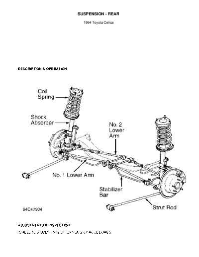
         Major suspension components are MacPherson struts, connected
between rear axle carrier and vehicle body. Wheel bearings are mounted
in axle hub, bolted to rear axle carrier. See Fig. 1.


Fig. 1: Rear Suspension Components ID
Courtesy of Toyota Motor Sales, U.S.A., Inc.

    ADJUSTMENTS & INSPECTION

    WHEEL ALIGNMENT SPECIFICATIONS & PROCEDURES
NOTE:    See WHEEL ALIGNMENT SPECIFICATIONS & PROCEDURES article
         in the WHEEL ALIGNMENT section.
    WHEEL BEARING INSPECTION
         Raise and support vehicle. Remove wheel. Position dial
indicator with stem against center if axle shaft. Move axle shaft in
and out while observing dial indicator. Replace bearings if axial play
exceeds 0.002" (0.05 mm). Measure hub axial runout. Replace bearings
if runout exceeds 0.0028" (0.07 mm).

    WHEEL BEARING ADJUSTMENT
         Bearings must be replaced if axle shaft nut is tightened to
specification and axial play exceeds 0.002" (0.05 mm). No adjustment
is available.

    REMOVAL & INSTALLATION

    AXLE HUB, CARRIER & SHAFT
         Removal
         1) Raise and support vehicle. Remove rear wheels. On models
with ABS, remove rear speed sensor. On drum brake models, disconnect
brakeline (tube) at wheel cylinder. Plug openings. Remove brake drum.
See Fig. 1.
         2) On disc brake models, remove caliper, leaving hose
attached, and hang aside. Remove rotor. Remove axle hub-to-axle
carrier bolts, axle hub, and "O" ring.

CAUTION: Be careful not to damage ABS sensor rotor.

         3) Remove nuts and bolts retaining axle carrier to strut
assembly and suspension arms. Note position of nuts on suspension arms
and strut rods for installation reference. Remove axle carrier.

         Installation
         To install, reverse removal procedure. Install new "O" ring.
Tighten all fasteners to specification. See TORQUE SPECIFICATIONS.
Check rear wheel alignment. Bleed brake system.

NOTE:   Tighten axle carrier-to-strut assembly and suspension arms
        bolts to specification with vehicle at normal operating
        height. Bounce vehicle several times to stabilize suspension.

    STRUT ASSEMBLY
         Removal
         1) Raise and support vehicle. On vehicles with ABS, detach
speed sensor wire from strut. Remove clip and brake line at strut. On
disc brake models, remove caliper, leaving hose attached, and hang
aside.
         2) Disconnect stabilizer bar link (if equipped) from strut.
Support axle carrier with jack. Remove strut-to-axle carrier bolts.
Remove strut-to-body nuts. Remove strut assembly.

NOTE:   If strut is to be disassembled, loosen, but do not remove
        strut shaft nut before removing strut.

         Inspection
         Compress and extend shock rod to check for abnormal
resistance or noise. Push shock absorber piston rod in fully and
release. Piston rod should return at a constant speed throughout its
travel. If shock is defective, replace as an assembly. If shock is
defective, replace as an assembly.

CAUTION: To prevent personal injury, discharge gas from old shock
         absorber prior to its disposal. Drill a hole 0.08-0.12"
         (2-3 mm) in diameter above lower mounting bracket on
         cylinder.

         Installation
         To install, reverse removal procedure. Tighten fasteners to
specification. See TORQUE SPECIFICATIONS. Bleed brake system (if
necessary).

    SUSPENSION ARMS
         Removal
         Raise and support vehicle. On vehicles with ABS, detach speed
sensor wire clamp from suspension arms. Remove strut rod. Remove fuel
tank protector. Support suspension member. Mark cam plate, No. 2
(rear) suspension arm, and body for reassembly reference. Remove
remaining suspension arm retaining bolts. Remove suspension arms.

NOTE:    Note orientation of suspension arm installation for
         reassembly reference.

         Installation
         1) To install, reverse removal procedure. Take care to
install components at original locations.

         2) Temporarily install all bolts, leaving them loose. Install
wheels. Lower vehicle. Bounce vehicle several times to stabilize
suspension.
         3) Align reference marks on cam plate, No. 2 (rear)
suspension arm, and body. Tighten bolts to specification with vehicle
weight on suspension. See TORQUE SPECIFICATIONS. Check rear wheel
alignment. See WHEEL ALIGNMENT SPECIFICATIONS & PROCEDURES article in
the WHEEL ALIGNMENT section.

    STABILIZER BAR
         Removal
         Raise and support vehicle. Remove wheels. Use jack and wooden
block to support fuel tank. Remove tank band bolts from body. Lower
fuel tank slightly. Disconnect stabilizer bar from stabilizer bar
link. Remove stabilizer brackets and stabilizer bar.

         Installation
         To install, reverse removal procedure. Tighten bolts to
specification. See TORQUE SPECIFICATIONS.

    WHEEL BEARINGS
         Removal
         1) Raise and support vehicle. Remove rear wheels. Remove axle
hub-to-carrier bolts, axle hub, and "O" ring.
         2) Loosen staked part of axle shaft nut. Remove axle nut.
Using Puller (09950-20017), remove axle shaft from axle hub. Remove
inner bearing race. Using puller, remove outer bearing inner race.
Remove oil seal. Press bearing from axle hub.

         Installation
         1) Coat outside of new bearing with grease. Press new bearing
into axle hub. Install outer bearing inner race.
         2) Coat oil seal lip with grease. Drive oil seal into axle
hub. Install inner bearing inner race. Using Adapter (09636-20010),
press inner races onto axle shaft. Tighten axle shaft nut to
specification. Stake axle shaft nut. To install remaining components,
reverse removal procedure. Tighten all bolts to specification. See
TORQUE SPECIFICATIONS.

        STRUT ROD
         Removal & Installation
         1) Raise and support vehicle. Remove wheels. Remove nuts and
bolts holding strut rod to axle carrier and body. Remove strut rod.
         2) Install strut rod, leaving it loose. Temporarily install
all bolts, leaving them loose. Lower vehicle. Bounce vehicle to settle
suspension. Tighten all bolts to specification with vehicle weight on
suspension. See TORQUE SPECIFICATIONS.

        TORQUE SPECIFICATIONS
TORQUE SPECIFICATIONS TABLE
◦ Jabse Service Manual Search 2026 ◦ Jabse Pravopis ◦ onTap.bg ◦ Other service manual resources online : Fixya ◦ eServiceinfo