Service Manuals, User Guides, Schematic Diagrams or docs for : . Car Manuals Toyota Celica 1988-1989.1993-1994.2000 Approved Toyota Celica 1993 AIR_BAG_
<< Back | HomeMost service manuals and schematics are PDF files, so You will need Adobre Acrobat Reader to view : Acrobat Download Some of the files are DjVu format. Readers and resources available here : DjVu Resources
For the compressed files, most common are zip and rar. Please, extract files with Your favorite compression software ( WinZip, WinRAR ... ) before viewing. If a document has multiple parts, You should download all, before extracting.
Good luck. Repair on Your own risk. Make sure You know what You are doing.
Image preview - the first page of the document
>> Download AIR_BAG_ documenatation <<
Text preview - extract from the document
AIR BAG RESTRAINT SYSTEM
1993 Toyota Celica
1993 ACCESSORIES/SAFETY EQUIPMENT
Toyota Air Bags
Celica
WARNING: To avoid injury from accidental air bag deployment, read and
carefully follow all WARNINGS and SERVICE PRECAUTIONS.
DESCRIPTION & OPERATION
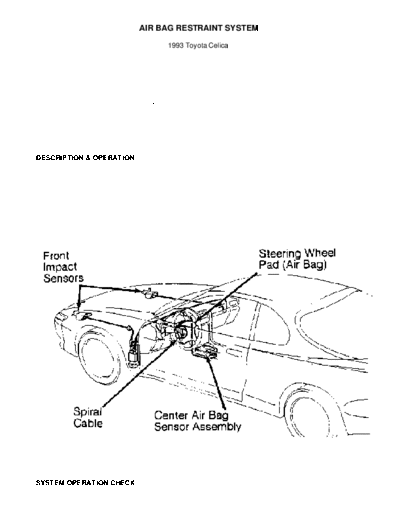
The Supplement Restraint System (SRS) consists of an AIR
BAG/SRS warning light in the instrument cluster, left and right front
impact sensors, steering wheel pad, spiral cable and center air bag
sensor. Steering wheel pad contains inflator and bag assembly. Center
air bag sensor assembly contains the back-up power source circuit,
safety circuit, safing sensor, memory circuit, diagnostic circuit,
ignition control and drive circuits. See Fig. 1.
The SRS is designed to deploy when the front-to-rear shock
is greater than a specified value. The ignition control and drive
circuits calculate signals from the center air bag sensor, deploying
air bag.
Fig. 1: SRS Component Location
Courtesy of Toyota Motor Sales, U.S.A., Inc.
SYSTEM OPERATION CHECK
Turn ignition switch to ACC or ON position. AIR BAG/SRS
warning light in instrument cluster should glow and go out after about
6 seconds. If AIR BAG/SRS warning light glows for more than 6 seconds
with ignition switch in ACC or ON position, SRS system is
malfunctioning and needs repair. If AIR BAG/SRS warning light glows
with ignition off, a short circuit is likely in AIR BAG/SRS warning
light circuit. See DIAGNOSIS & TESTING.
SERVICE PRECAUTIONS
Observe following precautions when working with air bag
systems:
* Disable SRS before servicing any SRS or steering column
component. Failure to do this could result in accidental air
bag deployment and possible personal injury. See DISABLING &
ACTIVATING AIR BAG SYSTEM.
* When trouble shooting SRS, always check for diagnostic codes
before disconnecting battery.
* After turning ignition switch to LOCK position and
disconnecting negative battery cable, wait at least 90
seconds before working on SRS. SRS is equipped with a back-up
power source that may allow air bag to deploy up to 90
seconds after negative battery cable is disconnected.
* In a minor collision in which air bag does not deploy, front
air bag sensors and steering wheel pad should be inspected.
* NEVER use air bag parts from another vehicle. Replace air bag
parts using new parts.
* Remove air bag sensors if shocks are likely to be applied to
sensors during repairs.
* Center air bag sensor assembly contains mercury. After
replacement, DO NOT destroy old part. When scrapping vehicle
or replacing center air bag sensor assembly, remove center
air bag sensor assembly and dispose of as toxic waste.
* Never disassemble and repair front air bag sensors, center
air bag sensor assembly or steering wheel pad.
* If front air bag sensors, center air bag sensor assembly or
steering wheel pad is dropped or if cracks, dents or other
defects exist in case, bracket or connector, replace parts
using new ones.
* DO NOT expose front air bag sensors, center air bag sensor
assembly or steering wheel pad directly to hot air or flame.
* Use a volt-ohmmeter with high impedance (10 k/ohm minimum)
for trouble shooting electrical circuit.
* Information labels are attached to air bag components. Follow
all notices on labels.
* After work on SRS is completed, check AIR BAG/SRS warning
light to ensure system is functioning properly. See SYSTEM
OPERATION CHECK.
* Always wear safety glasses when servicing or handling an air
bag.
* When placing a live air bag on a bench or other surface,
always face air bag and trim cover up, away from surface.
This will reduce motion of module if it is accidentally
deployed.
* After deployment, air bag surface may contain deposits of
sodium hydroxide, which irritates skin, from gas generant
combustion. Always wear safety glasses, rubber gloves and
long-sleeved shirt during clean-up, and wash hands using mild
soap and water.
* When carrying a live air bag module, trim cover should be
pointed away from your body to minimize injury in case of
accidental deployment.
* If SRS is not fully functional for any reason, vehicle should
not be driven until system is repaired and again becomes
operational. DO NOT remove bulbs, modules, sensors or other
components or in any way disable system from operating
normally. If SRS is not functional, park vehicle until it is
repaired and functions properly.
DISABLING & ACTIVATING AIR BAG SYSTEM
WARNING: Back-up power supply maintains SRS voltage for about 90
seconds after battery is disconnected. After disabling SRS,
wait at least 90 seconds before servicing SRS to prevent
accidental air bag deployment and possible personal injury.
To disable SRS, turn ignition switch to LOCK position and
disconnect negative battery cable. Wait at least 90 seconds before
servicing SRS. To activate SRS, reconnect negative battery cable.
Perform SYSTEM OPERATION CHECK.
DISPOSAL PROCEDURES
DEPLOYED AIR BAG
Deployed air bag modules can be disposed of as would any
other part. Handle air bag module wearing gloves and safety glasses.
SCRAPPED VEHICLE
NOTE: Some vehicles to be scrapped may have an undeployed air bag.
When scrapping vehicles equipped with SRS, deploy air bag
module.
1) Before proceeding, follow service precautions. See SERVICE
PRECAUTIONS. Disable SRS. See DISABLING & ACTIVATING AIR BAG SYSTEM.
Ensure steering wheel and steering wheel pad are not loose. If
steering wheel and steering wheel pad are loose, air bag cannot be
deployed using this procedure. Follow procedure listed under
UNDEPLOYED AIR BAG.
2) Remove instrument panel lower finish panel. Disconnect
spiral cable air bag connector, located on lower steering column.
Connect Deployment Tool (09082-00700) connector to spiral cable air
bag connector. Position deployment tool at least 33 feet from front of
vehicle.
3) Close all doors and windows of vehicle. Connect deployment
tool Red clip to positive battery terminal and Black clip to negative
battery terminal. Ensuring no one is inside or within 33 feet of
vehicle, press activation switch to deploy air bag. Because of heat,
DO NOT touch air bag for at least 30 minutes after deployment.
UNDEPLOYED AIR BAG
1) Never dispose of a steering wheel pad with an undeployed
air bag. Never deploy an air bag inside a vehicle, unless vehicle is
to be scrapped.
2) Before proceeding, see SERVICE PRECAUTIONS. Disable SRS.
See DISABLING & ACTIVATING AIR BAG SYSTEM. Remove steering wheel pad
from vehicle. See STEERING WHEEL PAD & SPIRAL CABLE under REMOVAL &
INSTALLATION.
3) To deploy a loose steering wheel pad, manufacturer
recommends installing pad to a scrap vehicle wheel rim and tire
assembly. To do so, install 4 bolts in holes provided in rear of
steering wheel pad. Tighten bolts by hand until they become difficult
to turn. DO NOT overtighten bolts.
4) Wrap strong wire at least twice around bolts on left and
right sides of steering wheel pad. See Fig. 2. Ensure no slack is
present in wire. If slack is present, or wire is not strong enough,
steering wheel pad may become loose due to shock when air bag is
deployed.
5) Position steering wheel pad on wheel rim and tire assembly
with pad side facing upward. Ensuring wire is tight, separately tie
left and right sides of steering wheel pad to wheel rim through lug
nut holes. See Fig. 3.
6) Connect Deployment Tool (09082-00700) to steering wheel
pad connector. Position deployment tool at least 33 feet from steering
wheel pad. Place a large cardboard box (weighted at sides) or 3 scrap
tires on top of steering wheel pad. Ensure no one is within 33 feet of
steering wheel pad. Press activation switch to deploy air bag.
7) Because of heat, wait 30 minutes before handling air bag.
Use Gloves and safety glasses when handling a steering wheel pad with
deployed air bag.
Fig. 2: Installing Wire On Steering Wheel Pad
Courtesy of Toyota Motor Sales, U.S.A., Inc.
Fig. 3: Installing Steering Wheel Pad On Wheel Assembly
Courtesy of Toyota Motor Sales, U.S.A., Inc.
POST-COLLISION INSPECTION
Check diagnostic system. See SELF-DIAGNOSTIC SYSTEM under
DIAGNOSIS & TESTING. Replace center air bag sensor if air bag
deployed. Remove steering wheel pad and air bag assembly. Check for
following conditions and replace components as necessary:
* Cut, cracked or markedly discolored steering wheel pad top
surface and steering wheel pad grooved portion.
* Cut, cracked or chipped connectors or wire harnesses.
* Deformity of horn button contact plate and front air bag
sensor bracket.
* Peeling off of label or damage to series number on front air
bag sensor.
WARNING: If horn button contact plate is deformed, never repair it.
Instead, replace entire steering wheel assembly. Ensure
steering wheel pad does not contact steering wheel.
Clearance must be uniform all the way around steering wheel
pad.
REMOVAL & INSTALLATION
WARNING: Failure to follow air bag service precautions may result in
air bag deployment and personal injury. See SERVICE
PRECAUTIONS. After component replacement, perform a system
operational check to ensure proper system operation. See
SYSTEM OPERATION CHECK.
CENTER AIR BAG SENSOR
Removal & Installation
1) Before proceeding, follow air bag service precautions. See
SERVICE PRECAUTIONS. Disable SRS. See DISABLING & ACTIVATING AIR BAG
SYSTEM.
2) Center air bag sensor is located underneath console.
Remove center console trim panel. See Fig. 4. Remove 4 screw covers
from sides of center console box. Remove 4 center console screws and 2
bolts. Remove center console box.
3) Remove scuff plates. Remove 4 screws, glove box and
passenger-side lower trim panel. Remove engine hood release lever.
Remove screw covers, 6 screws and instrument cluster lower trim panel.
NOTE: Disconnect center air bag sensor electrical connector before
removing sensor attaching screws.
4) Remove 2 screws and radio trim panel. Remove 4 screws and
radio. Remove screw covers and 4 screws from center console. Remove
instrument panel brace. See Fig. 4. Disconnect center air bag sensor
assembly electrical connector. Remove 4 screws and center air bag
sensor assembly.
5) To install, reverse removal procedure. Tighten center air
bag sensor screws to specification. See TORQUE SPECIFICATIONS.
Reactivate SRS. Ensure system is functioning properly. See SYSTEM
OPERATION CHECK.
Fig. 4: Removing Center Air Bag Sensor Assembly
Courtesy of Toyota Motor Sales, U.S.A., Inc.
FRONT AIR BAG SENSORS
Removal & Installation
1) Before proceeding, follow air bag service precautions. See
SERVICE PRECAUTIONS. Disable SRS. See DISABLING & ACTIVATING AIR BAG
SYSTEM.
2) Front air bag sensors are located in left and right fender
areas. Remove screws and clips attaching inner fender shield to
vehicle.
3) Remove hood lock protector plate or inner fender shield.
Disconnect front air bag sensor electrical connector. Remove 2 bolts
attaching sensor to fender. Remove front air bag sensor.
4) To install, reverse removal procedure. Ensure arrow marks
on sensors face front of vehicle. Tighten front air bag sensor bolts
to specification. See TORQUE SPECIFICATIONS. Reactivate SRS. Check AIR
BAG warning light to ensure system is functioning properly. See SYSTEM
OPERATION CHECK.
STEERING WHEEL PAD & SPIRAL CABLE
Removal & Installation
1) Ensure front wheels are in straight-ahead position. Before
proceeding, see SERVICE PRECAUTIONS. Disable SRS. See DISABLING &
ACTIVATING AIR BAG SYSTEM. Remove driver-side scuff plate.
2) Remove engine hood release lever. Remove screw covers, 6
screws and lower instrument cluster trim panel(s). Loosen 4 steering
wheel pad Torx screws until groove along screw circumference catches
on screw case. See Figs. 5 and 6.
3) Pull steering wheel pad from steering wheel and disconnect
steering wheel pad (squib) connector. Remove steering wheel pad
assembly. Place steering wheel pad assembly on a flat surface with pad
cover facing up.
4) Place a mark on steering wheel and main shaft for
installation reference. Using steering wheel puller, remove steering
wheel. Remove 4 screws from upper and lower steering column covers.
5) Remove screws attaching spiral cable to combination
(headlight/turn signal/wiper) switch. Disconnect spiral cable and
remove from vehicle.
6) To install, reverse removal procedure. Before installing
spiral cable, ensure spiral cable is properly aligned. See SPIRAL
CABLE under ADJUSTMENTS. Tighten steering wheel nut and steering wheel
pad screws to specification. See TORQUE SPECIFICATIONS.
7) After spiral cable and steering wheel pad are installed,
reactivate SRS. Ensure proper SRS operation. See SYSTEM OPERATION
CHECK.
Fig. 5: Removing Steering Wheel Pad
Courtesy of Toyota Motor Sales, U.S.A., Inc.
Fig. 6: Exploded View Of Steering Wheel Pad
Courtesy of Toyota Motor Sales, U.S.A., Inc.
ADJUSTMENTS
SPIRAL CABLE
Ensure front wheels are in straight-ahead position. Turn
spiral cable counterclockwise until it stops. Turn spiral cable
clockwise 2.5 turns. Mating marks should align with Red mark. See
Fig. 7. Ensure mating marks are aligned and install steering wheel.
Fig. 7: Aligning Spiral Cable
Courtesy of Toyota Motor Sales, U.S.A., Inc.
WIRE REPAIR
CAUTION: If air bag wiring harness is damaged, replace complete
wiring harness assembly. Following WIRE REPAIR procedure is
to be used only to repair connector to front air bag
sensors.
1) Repair wire using 2 Pressure-Contact Sleeves (82988-
50010); sleeves are available for repairing air bag connector
problems. To repair, uncover front air bag sensor connector to be
repaired. Leaving wires as long as possible, cut wiring harness behind
connector. Carefully strip .31-.43" insulation from each wire to be
repaired. DO NOT damage wire during this operation. If any damage
exists, perform stripping operation again.
2) Overlap 2 stripped wire ends inside pressure-contact
sleeve. Using Crimper (169060-2), place sleeve in correct color-keyed
section of tool. With center of sleeve between crimping jaws, squeeze
tool until either end comes in contact at section of tool marked CLOSE
HERE.
3) Pull joined wires on both ends to ensure a secure crimp.
Crimp both ends of sleeve using crimper at INS position. See Fig. 8.
Thoroughly wrap silicon tape around joint for protection.
Fig. 8: Crimping Pressure-Contact Sleeve
Courtesy of Toyota Motor Sales, U.S.A., Inc.
TORQUE SPECIFICATIONS
TORQUE SPECIFICATIONS
◦ Jabse Service Manual Search 2026 ◦ Jabse Pravopis ◦ onTap.bg ◦ Other service manual resources online : Fixya ◦ eServiceinfo