Service Manuals, User Guides, Schematic Diagrams or docs for : . Car Manuals Toyota Celica 1988-1989.1993-1994.2000 Approved Toyota Celica 2000 Toyota Celica 2000 Service Manual Engine ARTICLE_REPLACE_CONNECTORS_ECM
<< Back | HomeMost service manuals and schematics are PDF files, so You will need Adobre Acrobat Reader to view : Acrobat Download Some of the files are DjVu format. Readers and resources available here : DjVu Resources
For the compressed files, most common are zip and rar. Please, extract files with Your favorite compression software ( WinZip, WinRAR ... ) before viewing. If a document has multiple parts, You should download all, before extracting.
Good luck. Repair on Your own risk. Make sure You know what You are doing.
Image preview - the first page of the document
>> Download ARTICLE_REPLACE_CONNECTORS_ECM documenatation <<
Text preview - extract from the document
Page 1 of 6
How to Replace Terminals

How to Replace Terminals


  ZOOM           SIZED FOR PRINT

With Terminal Retainer or Secondary Locking Device


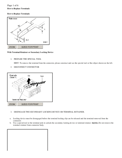
   1. PREPARE THE SPECIAL TOOL

       HINT: To remove the terminal from the connector, please construct and use the special tool or like object shown on the left.

   2. DISCONNECT CONNECTOR


  ZOOM           SIZED FOR PRINT


   3. DISENGAGE THE SECONDARY LOCKING DEVICE OR TERMINAL RETAINER.


  a.   Locking device must be disengaged before the terminal locking clip can be released and the terminal removed from the
       connector.
  b.   Use a special tool or the terminal pick to unlock the secondary locking device or terminal retainer. NOTE: Do not remove the
       terminal retainer from connector body.
Page 2 of 6


  ZOOM            SIZED FOR PRINT

A - For Non-Waterproof Type Connector

HINT : The needle insertion position varies according to the connector's shape (number of terminals etc.), so check the position
before inserting it.

"Case 1"
Raise the terminal retainer up to the temporary lock position.


  ZOOM            SIZED FOR PRINT

"Case 2"
Open the secondary locking device.
Page 3 of 6


  ZOOM             SIZED FOR PRINT


  ZOOM             SIZED FOR PRINT

B - For Waterproof Type Connector

HINT: Terminal retainer color is different according to connector body.

Example:


  Terminal Retainer : Connector Body

  Black or White      : Gray

  Black or White      : Dark Gray

  Gray or White       : Black
Page 4 of 6


  ZOOM            SIZED FOR PRINT

"Case 1"
Type where terminal retainer is pulled up to the temporary lock position (Pull Type).

Insert the special tool into the terminal retainer access hole ( Mark) and pull the terminal retainer up to the temporary lock position.

HINT: The needle insertion position varies according to the connector's shape (Number of terminals etc.), so check the position
before inserting it.


  ZOOM            SIZED FOR PRINT

"Case 2"
Type which cannot be pulled as far as Power Lock insert the tool straight into the access hole of terminal retainer as shown.
Page 5 of 6


  ZOOM            SIZED FOR PRINT

Push the terminal retainer down to the temporary lock position.


  ZOOM            SIZED FOR PRINT


   c.   Release the locking lug from terminal and pull the terminal out from rear.


  ZOOM            SIZED FOR PRINT
Page 6 of 6
   4. INSTALL TERMINAL TO CONNECTOR


  a.   Insert the terminal. HINT:

          1. Make sure the terminal is positioned correctly.
          2. Insert the terminal until the locking lug locks firmly.
          3. Insert the terminal with terminal retainer in the temporary lock position.


 ZOOM            SIZED FOR PRINT


  b.   Push the secondary locking device or terminal retainer in to the full lock position.


   5. CONNECT CONNECTOR
◦ Jabse Service Manual Search 2026 ◦ Jabse Pravopis ◦ onTap.bg ◦ Other service manual resources online : Fixya ◦ eServiceinfo