Service Manuals, User Guides, Schematic Diagrams or docs for : . Car Manuals Toyota Celica 1988-1989.1993-1994.2000 Approved Toyota Celica 2000 Toyota Celica 2000 Service Manual Interior ARTICLE_TENSIONER_REPLACEMENT
<< Back | HomeMost service manuals and schematics are PDF files, so You will need Adobre Acrobat Reader to view : Acrobat Download Some of the files are DjVu format. Readers and resources available here : DjVu Resources
For the compressed files, most common are zip and rar. Please, extract files with Your favorite compression software ( WinZip, WinRAR ... ) before viewing. If a document has multiple parts, You should download all, before extracting.
Good luck. Repair on Your own risk. Make sure You know what You are doing.
Image preview - the first page of the document
>> Download ARTICLE_TENSIONER_REPLACEMENT documenatation <<
Text preview - extract from the document
Page 1 of 25
Service and Repair

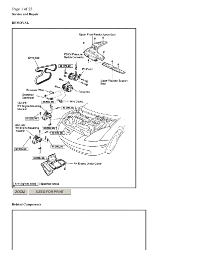
REMOVAL


  ZOOM         SIZED FOR PRINT


Related Components
Page 2 of 25


 ZOOM          SIZED FOR PRINT


1ZZ-FE
Page 3 of 25


 ZOOM           SIZED FOR PRINT


2ZZ-GE

  1.   REMOVE UPPER FRONT FENDER APRON SEAL AND UPPER RADIATOR SUPPORT SEAL
  2.   DRAIN ENGINE COOLANT
  3.   REMOVE RIGHT-HAND FRONT WHEEL
  4.   REMOVE RIGHT-HAND ENGINE UNDER COVER
  5.   REMOVE DRIVE BELT AND GENERATOR
  6.   DISCONNECT PS PUMP FROM ENGINE

         a.   Disconnect the PS oil pressure switch connector.
         b.   Remove the 2 nuts and through bolts, and disconnect the PS pump from the engine. HINT: Put aside the pump and
Page 4 of 25
              suspend it to the cowl with a string.

  7.   REMOVE RIGHT-HAND ENGINE MOUNTING INSULATOR


 ZOOM            SIZED FOR PRINT


  a.   Set the jack to the engine. HINT: Place a wooden block between the jack and engine.
  b.   1ZZ-FE: Remove the 4 bolts, 2 nuts and Right-Hand engine mounting insulator.


 ZOOM            SIZED FOR PRINT


  c.   2ZZ-GE: Remove the 5 bolts, 2 nuts and Right-Hand engine mounting insulator.


 ZOOM            SIZED FOR PRINT


  8.   1ZZ-FE: REMOVE CYLINDER HEAD COVER

          a. Remove the 4 bolts and No. 2 cylinder head cover.
          b. Remove the 4 ignition coils.
          c. Disconnect the 2 PCV hoses from the cylinder head.
          d. Remove the 9 bolts, 2 seal washers, 2 nuts, cylinder head cover and gasket.
Page 5 of 25
  9.   2ZZ-GE: REMOVE CYLINDER HEAD COVER

          a. Remove the 4 bolts and No. 2 cylinder head cover.
          b. Remove the ignition coils.
          c. Disconnect the 2 PCV hoses from the cylinder head cover.


 ZOOM            SIZED FOR PRINT


          d.   Remove the 2 nuts, bolt and disconnect the No. 3 ventilation hose from the No. 1 ventilation pipe.
          e.   Remove the No. 1 ventilation pipe and gasket.


 ZOOM            SIZED FOR PRINT


          f.   Remove the 9 bolts, wire harness protector, cylinder head cover and gasket.

 10.   SET NO. 1 CYLINDER TO TDC/COMPRESSION


 ZOOM            SIZED FOR PRINT


  a.   Turn the crankshaft pulley, and align its groove with timing mark "0" of the timing chain cover.
Page 6 of 25


 ZOOM            SIZED FOR PRINT


  b.   Check that the point marks of the camshaft timing sprockets are in straight line on the timing chain cover surface as shown in
       the illustration. If not, turn the crankshaft 1 revolution (360
◦ Jabse Service Manual Search 2026 ◦ Jabse Pravopis ◦ onTap.bg ◦ Other service manual resources online : Fixya ◦ eServiceinfo