Service Manuals, User Guides, Schematic Diagrams or docs for : . Car Manuals Toyota Celica 1988-1989.1993-1994.2000 Approved Toyota Celica 2000 Toyota Celica 2000 Service Manual Suspension ARTICLE_SUSPENSION_LOWER_CONTROL_ARM_REAR_SERVICE
<< Back | HomeMost service manuals and schematics are PDF files, so You will need Adobre Acrobat Reader to view : Acrobat Download Some of the files are DjVu format. Readers and resources available here : DjVu Resources
For the compressed files, most common are zip and rar. Please, extract files with Your favorite compression software ( WinZip, WinRAR ... ) before viewing. If a document has multiple parts, You should download all, before extracting.
Good luck. Repair on Your own risk. Make sure You know what You are doing.
Image preview - the first page of the document
>> Download ARTICLE_SUSPENSION_LOWER_CONTROL_ARM_REAR_SERVICE documenatation <<
Text preview - extract from the document
Page 1 of 2
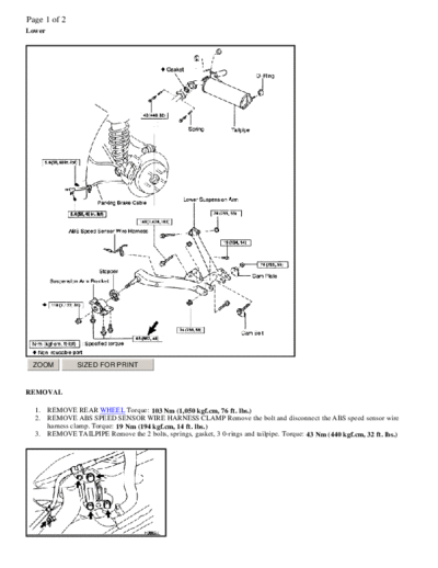
Lower


 ZOOM            SIZED FOR PRINT


REMOVAL

  1.    REMOVE REAR WHEEL Torque: 103 Nm (1,050 kgf.cm, 76 ft. lbs.)
  2.    REMOVE ABS SPEED SENSOR WIRE HARNESS CLAMP Remove the bolt and disconnect the ABS speed sensor wire
        harness clamp. Torque: 19 Nm (194 kgf.cm, 14 ft. lbs.)
  3.    REMOVE TAILPIPE Remove the 2 bolts, springs, gasket, 3 0-rings and tailpipe. Torque: 43 Nm (440 kgf.cm, 32 ft. lbs.)
Page 2 of 2
  ZOOM            SIZED FOR PRINT


   4.   DISCONNECT PARKING BRAKE CABLE CLAMP Remove the 2 bolts and disconnect the parking brake cable clamps.
        Torque: 5.4 Nm (55 kgf.cm, 48 inch lbs.)
   5.   LOOSEN 3 BOLTS ON FRONT SIDE OF LOWER SUSPENSION ARM Torque: 65 Nm (663 kgf.cm, 48 ft. lbs.) HINT:
        Do not remove the bolts. At the time of installation, after stabilizing the suspension, torque the bolts.


  ZOOM            SIZED FOR PRINT


   6.   DISCONNECT REAR AXLE CARRIER FROM LOWER SUSPENSION ARM

           a. Remove the front side bolt and nut. Torque: 74 Nm (755 kgf.cm, 55 ft. lbs.) HINT: At the time of installation, after
              stabilizing the suspension, torque the nut.
           b. Place matchmarks on both the cam plate and lower suspension arm.
           c. Remove the nut, cam plate and cam bolt. Torque: 74 Nm (755 kgf.cm, 55 ft. lbs.) HINT: At the time of installation,
              after stabilizing the suspension, torque the nut.
           d. Disconnect the rear axle carrier from the lower suspension arm.

   7.   DISCONNECT REAR SHOCK ABSORBER Remove the bolt and nut and disconnect the rear shock absorber. Torque: 140
        Nm (1,428 kgf.cm, 103 ft. lbs.) NOTICE: Do not turn the nut. HINT: At the time of installation, after stabilizing the
        suspension, torque the bolt.
   8.   REMOVE LOWER SUSPENSION ARM

           a. Remove the bolt and nut on the rear side of lower suspension arm. Torque: 74 Nm (755 kgf.cm, 55 ft. lbs.) HINT: At
              the time of installation, after stabilizing the suspension, torque the nut.
           b. Remove the front side 3 bolts and lower suspension arm.


  ZOOM            SIZED FOR PRINT


   9.   REMOVE SUSPENSION ARM BRACKET Remove the nut, suspension arm bracket and stopper. Torque: 110 Nm (1,122
        kgf.cm, 81 ft. lbs.) HINT: At the time of installation, after stabilizing the suspension, torque the nut.

INSTALLATION
Installation is in the reverse order of removal.

HINT: After installation, check the rear wheel alignment.
◦ Jabse Service Manual Search 2026 ◦ Jabse Pravopis ◦ onTap.bg ◦ Other service manual resources online : Fixya ◦ eServiceinfo