Service Manuals, User Guides, Schematic Diagrams or docs for : . Car Manuals Toyota Celica 1988-1989.1993-1994.2000 Approved Toyota Celica 2000 Toyota Celica 2000 Service Manual Suspension ARTICLE_SUSPENSION_STABILIZER_BAR_REAR_SERVICE
<< Back | HomeMost service manuals and schematics are PDF files, so You will need Adobre Acrobat Reader to view : Acrobat Download Some of the files are DjVu format. Readers and resources available here : DjVu Resources
For the compressed files, most common are zip and rar. Please, extract files with Your favorite compression software ( WinZip, WinRAR ... ) before viewing. If a document has multiple parts, You should download all, before extracting.
Good luck. Repair on Your own risk. Make sure You know what You are doing.
Image preview - the first page of the document
>> Download ARTICLE_SUSPENSION_STABILIZER_BAR_REAR_SERVICE documenatation <<
Text preview - extract from the document
Page 1 of 2
Rear


 ZOOM           SIZED FOR PRINT


REMOVAL

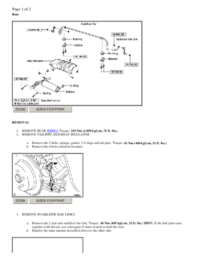
  1.   REMOVE REAR WHEEL Torque: 103 Nm (1,050 kgf.cm, 76 ft. lbs.)
  2.   REMOVE TAILPIPE AND HEAT INSULATOR

         a. Remove the 2 bolts, springs, gasket, 3 0-rings and tail pipe. Torque: 43 Nm (440 kgf.cm, 32 ft. lbs.)
         b. Remove the 4 bolts and heat insulator.


 ZOOM           SIZED FOR PRINT


  3.   REMOVE STABILIZER BAR LINKS

         a.   Remove the 2 nuts and stabilizer bar link. Torque: 44 Nm (449 kgf.cm, 32 ft. lbs.) HINT: If the ball joint turns
              together with the nut, use a hexagon (5 mm) wrench to hold the stud.
         b.   Employ the same manner described above to the other side.
Page 2 of 2


  ZOOM            SIZED FOR PRINT


   4.   REMOVE STABILIZER BAR BRACKETS AND BUSHINGS

           a.   Remove the 2 bolts, bracket and bushing. Torque: 18 Nm (184 kgf.cm, 13 ft. lbs.) HINT: At the time of installation,
                install the bushing to the outside of the stopper on the stabilizer bar.
           b.   Employ the same manner described above to the other side.

   5.   REMOVE STABILIZER BAR

INSPECTION
INSPECT STABILIZER BAR LINK BALL JOINT FOR ROTATION CONDITION


  ZOOM            SIZED FOR PRINT


   a.   As shown in the illustration, flip the ball joint stud back and forth 5 times, before installing the nut.
   b.   Using a torque wrench, turn the nut continuously at a rate of 2 - 4 seconds per 1 turn and take the torque reading on the 5th
        turn. Turning torque: 0.05 - 1.0 Nm (0.5 - 10 kgf.cm, 0.4 - 8.7 inch lbs.)

INSTALLATION
Installation is in the reverse order of removal.
◦ Jabse Service Manual Search 2026 ◦ Jabse Pravopis ◦ onTap.bg ◦ Other service manual resources online : Fixya ◦ eServiceinfo