Service Manuals, User Guides, Schematic Diagrams or docs for : . Car Manuals Toyota Celica 1988-1989.1993-1994.2000 Approved Toyota Celica 2000 Toyota Celica 2000 Service Manual Technical Service Bulletins TSB_shifter_springs
<< Back | HomeMost service manuals and schematics are PDF files, so You will need Adobre Acrobat Reader to view : Acrobat Download Some of the files are DjVu format. Readers and resources available here : DjVu Resources
For the compressed files, most common are zip and rar. Please, extract files with Your favorite compression software ( WinZip, WinRAR ... ) before viewing. If a document has multiple parts, You should download all, before extracting.
Good luck. Repair on Your own risk. Make sure You know what You are doing.
Image preview - the first page of the document
>> Download TSB_shifter_springs documenatation <<
Text preview - extract from the document
Page 1 of 3
M/T, 6 Speed, Shift Spring - Update

TRANSMISSION

TC001-00

June 2, 2000

Title:
SHIFT SPRING UPDATE

Models:
'00 Celica GTS

Introduction

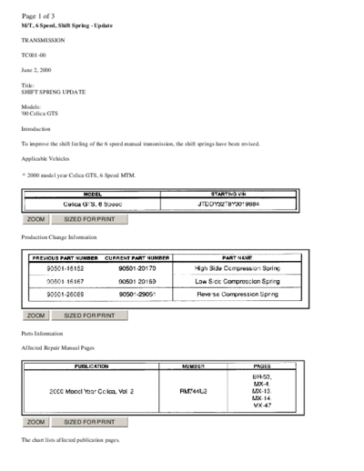
To improve the shift feeling of the 6 speed manual transmission, the shift springs have been revised.

Applicable Vehicles

^ 2000 model year Celica GTS, 6 Speed MTM.


  ZOOM              SIZED FOR PRINT


Production Change Information


  ZOOM              SIZED FOR PRINT


Parts Information

Affected Repair Manual Pages


  ZOOM              SIZED FOR PRINT


The chart lists affected publication pages.
Page 2 of 3


  ZOOM             SIZED FOR PRINT


Warranty Information

Applicable Warranty*:
This repair is covered under the Toyota Basic Warranty. This warranty is in effect for 36 months or 36,000 miles, whichever occurs
first, from the vehicle's in-service date.

* Warranty application is limited to correction of a problem based upon a customer's specific complaint.

Repair Procedure

1. Remove LH Engine Undercover, the Battery, Battery Tray and Engine ECU Box (MX-4, Steps 4 & 5). See the 2000 MY Celica
   Repair Manual listed pages for details.
2. Loosen the ABS Actuator bracket from the vehicle by removing the nuts & bolts (BR-53, Steps 6a & 6b) if equipped with ABS.
   The ABS Actuator will have to be moved out of the way when removing the Selector Shaft, but not removed from the vehicle.


  ZOOM             SIZED FOR PRINT


3. Remove the Selector Shaft by removing the Control Shift Lever, Lock Ball Assembly and the 4 bolts for the Selector Shaft
   Housing (MX-13 & MX-14, Steps 7, 8, & 10).
4. Remove the Reverse Compression Spring from the Selector Shaft Housing. Use caution when removing the Reverse Compression
   Spring as it is in compression (MX-14, Step 9)
Page 3 of 3
5. Remove the Low Side Compression Spring from the Selector Shaft.
6. Remove the High Side Compression Spring from the Selector Shaft by removing the E-Ring and Spring Seat for the High Side
   Compression Spring. Use caution when removing the High Side Spring as it is in compression (MX-47).
7. Assemble in the reverse order.
◦ Jabse Service Manual Search 2026 ◦ Jabse Pravopis ◦ onTap.bg ◦ Other service manual resources online : Fixya ◦ eServiceinfo