Service Manuals, User Guides, Schematic Diagrams or docs for : . Car Manuals Toyota Celica 1988-1989.1993-1994.2000 Approved Toyota Celica 2000 Toyota Celica 2000 Service Manual Transmission ARTICLE_MANUAL_TRANSAXLE_ASSMEBLY
<< Back | HomeMost service manuals and schematics are PDF files, so You will need Adobre Acrobat Reader to view : Acrobat Download Some of the files are DjVu format. Readers and resources available here : DjVu Resources
For the compressed files, most common are zip and rar. Please, extract files with Your favorite compression software ( WinZip, WinRAR ... ) before viewing. If a document has multiple parts, You should download all, before extracting.
Good luck. Repair on Your own risk. Make sure You know what You are doing.
Image preview - the first page of the document
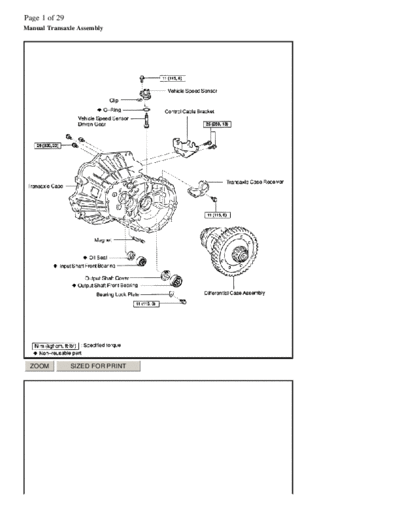
>> Download ARTICLE_MANUAL_TRANSAXLE_ASSMEBLY documenatation <<
Text preview - extract from the document
Page 1 of 29
Manual Transaxle Assembly


 ZOOM          SIZED FOR PRINT
Page 2 of 29


 ZOOM          SIZED FOR PRINT
Page 3 of 29


 ZOOM             SIZED FOR PRINT


DISASSEMBLY

  1.    REMOVE FILLER PLUG AND DRAIN PLUG WITH 2 GASKETS Torque: 39 Nm (400 kgf-cm, 29 ft. lbs.)
  2.    REMOVE VEHICLE SPEED SENSOR


 a)    Remove the bolt and vehicle speed sensor.
       Torque: 11 Nm (115 kgf-cm, 8 ft. lbs.)

 b) Using a small screwdriver, remove the clip from the vehicle speed sensor.
Page 4 of 29
 c)       Remove the vehicle speed sensor driven gear from the speed sensor.

 d) Using a small screwdriver, remove the O -ring from the vehicle speed sensor.


  3.       REMOVE BACK-UP LIGHT SWITCH WITH GASKET Torque: 40 Nm (410 kgf-cm, 30 ft. lbs.)
  4.       REMOVE CONTROL CABLE BRACKET Remove the 2 bolts and control cable bracket. Torque: 25 Nm (250 kgf-cm, 18 ft.
           lbs.)


 ZOOM                SIZED FOR PRINT


  5.       REMOVE CONTROL SHAFT ASSEMBLY Remove the 2 nuts, wave washer and control shaft assembly. Torque: 12 Nm
           (120 kgf-cm, 9 ft. lbs.)


 ZOOM                SIZED FOR PRINT


  6.       REMOVE SELECTING BELLCRANK ASSEMBLY


 a) Remove the 2 bolts and selecting bellcrank assembly.

          Torque: 25 Nm (250 kgf-cm, 18 ft. lbs.)


NOTICE:

      l    At the time of reassembly, please refer to the following item.
      l    Fit the selecting bellcrank assembly pin part with the dust cover into a groove in the control shift lever.


 b) Remove the control bellcrank dust cover from the selecting bellcrank assembly.


NOTICE:
Page 5 of 29
   l   At the time of reassembly, please refer to the following item.
   l   Apply MP grease to the inside circumferential surface of the control bellcrank dust cover.

  7.   REMOVE CONTROL SHIFT LEVER AND DUST BOOT


 ZOOM             SIZED FOR PRINT


 a) Remove the nut and wave washer.
    Torque:12 Nm (120 kgf-cm, 9 ft. lbs.)


 ZOOM             SIZED FOR PRINT


 b) Using a pin punch and hammer, drive out the lever lock pin.


NOTICE:

   l   At the time of reassembly, please refer to the following item.
   l   When fixing the lever lock pin, properly position the shaft groove.


 c) Remove the control shift lever and dust boot.


NOTICE:

   l   At the time of reassembly, please refer to the following items.
   l   Install the dust boot into a groove in the control shift lever.
   l   Be sure to install the dust boot in the correct direction, as shown in the illustration.
Page 6 of 29


 ZOOM             SIZED FOR PRINT


  8.    REMOVE PLUG, LOCK BALL ASSEMBLY AND CONTROL SHAFT COVER ASSEMBLY


 a)    Using a hexagon wrench, remove the plug and gasket.
       Torque: 39 Nm (400 kgf-cm, 29 ft. lbs.)

 b) Remove the lock ball assembly.
    Sealant:
    Part No. 08833-00080, THREE BOND 1344, LOCTITE 242 or equivalent
    Torque: 29 Nm (300 kgf-cm, 22 ft. lbs.)

 c)    Remove the 4 bolts and control shaft cover assembly with the gasket.
       Sealant:
       Part No. 08833-00080, THREE BOND 1344, LOCTITE 242 or equivalent
       Torque: 20 Nm (200 kgf-cm, 14 ft. lbs.)


 ZOOM             SIZED FOR PRINT


  9.    DISASSEMBLE CONTROL SHAFT COVER ASSEMBLY


 a)    Using snap ring pliers, remove the snap ring.

 b) Remove the No.3 select spring seat and compression spring.
Page 7 of 29


  ZOOM                 SIZED FOR PRINT


  10.       REMOVE SHIFT AND SELECT LEVER SHAFT ASSEMBLY


  a) Remove the shift and select lever shaft assembly.


NOTICE:

       l    At the time of reassembly, please refer to the following Item.
       l    Set the claws of the shift interlock plate into the shift head part of the gear shift fork shaft securely.


  b) Remove the select spring seat and compression spring from the shift and select lever shaft assembly.


  ZOOM                 SIZED FOR PRINT


  11.       REMOVE TRANSMISSION CASE COVER


  a)       Remove the 9 bolts.
           Torque: 18 Nm (185 kgf-cm, 13 ft. lbs.)

  b) Carefully tap the projection of the transmission case cover with a brass bar and hammer and remove it.


HINT: At the time of reassembly, please refer to the following item.
Apply FIPG to the transmission case side, as shown in the illustration.

FIPG: Part No. 08826-00090, THREE BOND 1281 or equivalent
Page 8 of 29


 ZOOM           SIZED FOR PRINT


 12.   INSPECT 6TH GEAR THRUST CLEARANCE Using a dial indicator, measure the thrust clearance. Standard clearance:0.10 -
       0.60 mm (0.0039 - 0.0236 inch) Maximum clearance: 0.60 mm (0.0236 inch)


 ZOOM           SIZED FOR PRINT


 13.   INSPECT 6TH GEAR RADIAL CLEARANCE Using a dial indicator, measure the radial clearance. Standard clearance:0.009
       - 0.050 mm (0.0003 - 0.0020 inch) Maximum clearance: 0.050 mm (0.0020 inch) If the clearance exceeds the maximum,
       replace the gear, needle roller bearing or shaft.
 14.   REMOVE OUTPUT SHAFT REAR RADIAL BALL BEARING, 6TH DRIVEN GEAR AND SPACER


 ZOOM           SIZED FOR PRINT


 a) Using 2 screwdrivers and a hammer, tap out the snap ring.
Page 9 of 29


 ZOOM             SIZED FOR PRINT


HINT:

   l    At the time of reassembly, please refer to the following item.
   l    Select a snap ring from the table that will make the thrust clearance of the output shaft rear radial ball bearing less than 0.1 mm
        (0.0039 inch).


 ZOOM             SIZED FOR PRINT


 b) Using SST, remove the rear radial ball bearing and 6th driven gear.
    SST 09950 -40011 (09951 -04010, 09952-04010, 09953-04030, 09954-04010, 09955-04021, 09957-04010, 09958-04011)


HINT:

   l    At the time of reassembly, please refer to the following items.


 ZOOM             SIZED FOR PRINT


   l    Using SST and a hammer, drive in the 6th driven gear. SST 09325-12010
Page 10 of 29
NOTICE: Be sure to install the 6th driven gear in the correct direction, as shown in the illustration.


  ZOOM            SIZED FOR PRINT


    l   Set SST to the rear radial ball bearing inner race securely, drive in the bearing with a hammer. SST 09517-12010


  c) Remove the spacer.


  15.   REMOVE INPUT SHAFT REAR RADIAL BALL BEARING AND 6TH GEAR


  ZOOM            SIZED FOR PRINT


  a) Using 2 screwdrivers and a hammer, tap out the snap ring.


  ZOOM            SIZED FOR PRINT


HINT:

    l   At the time of reassembly, please refer to the following item.
Page 11 of 29
   l    Select a snap ring from the table that will make the thrust clearance of the No.3 clutch hub less than 0.1 mm (0.0039 inch).


 ZOOM             SIZED FOR PRINT


 b) Using SST, remove the rear radial ball bearing and 6th gear.
    SST 09950 -40011 (09951 -04010, 09952-04010, 09953-04030, 09954-04010, 09955-04021, 09957-04010, 09958-04011)


 ZOOM             SIZED FOR PRINT


HINT:

   l    At the time of reassembly, please refer to the following item.
   l    Set SST to the rear radial ball bearing inner race securely, drive in the bearing with a hammer. SST 09517-12010


 c) Remove the needle roller bearing and spacer.


 ZOOM             SIZED FOR PRINT
Page 12 of 29
 16.   REMOVE NO.3 SYNCHRONIZER RING (FOR 6TH GEAR) NOTICE:
◦ Jabse Service Manual Search 2026 ◦ Jabse Pravopis ◦ onTap.bg ◦ Other service manual resources online : Fixya ◦ eServiceinfo