Service Manuals, User Guides, Schematic Diagrams or docs for : . Car Manuals Toyota Supra 1986-1987.1990.1995.1997 Approved Toyota Supra MK3 1987 Toyota-7M-Manual-EFI-FI
<< Back | HomeMost service manuals and schematics are PDF files, so You will need Adobre Acrobat Reader to view : Acrobat Download Some of the files are DjVu format. Readers and resources available here : DjVu Resources
For the compressed files, most common are zip and rar. Please, extract files with Your favorite compression software ( WinZip, WinRAR ... ) before viewing. If a document has multiple parts, You should download all, before extracting.
Good luck. Repair on Your own risk. Make sure You know what You are doing.
Image preview - the first page of the document
>> Download Toyota-7M-Manual-EFI-FI documenatation <<
Text preview - extract from the document
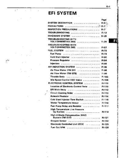
FI-1
i'.. ;
-EFI SYSTEM
..
Page
SYSTEM DESCRIPTION ....................... Fl-i.&.
;a""-
PRECAUTIONS ..............................
;;:",
.
F,-, ....
INSPECTION PRECAUTIONS .................... FI-7 .
TROUBLESHOOTING .......................... FI-12
DIAGNOSIS SYSTEM .................... . .... FI-25
TROUBLESHOOTING WITH
VOLT/OHMMETER (MA) .................... FI-34 m .:
TROUBLESHOOTING WITH
VOLT/OHMMETER (MS) .................... FI-57
FUEL SYSTEM ................................ FI-73,
Fuel Pump .................................. FI-73
Cold Start Injector ........................... Fl-80
Pressure Regulator .......................... FI'i84 ..
Injectors .............................. ..i .. FI-86
AIR INDUCTION SYSTEM ..................... FI-96
Air Flow Meter (7M-GE) ..................... FI-96
Air Flow Meter (7M-GTE) ................... FI-98
Throttle Body .............................. FI-102
Idle Speed Control (ISC) Valve ............... FI-108
ELECTRONIC CONTROL SYSTEM .............. FI-110
Location of Electronic Control Parts .......... FI-110
l
EFI Main Relay ............................. Fl-112
. Circuit Opening Relay ....................... FI-113
Solenoid Resistor ........................... Fl-114
Cold Start Injector Time Switch ............... FI-115
Water Temperature Sensor .................. FI-116
Fuel Pump Relay and Resistor ............... FI-117
i
`x High Temperature Line Pressure -
Up System ............................... FIi119
High Altitude Compensation (HACK
System (7M-GTE) ........................ FI-121
Oxygen Sensor ............................. FI-122
Electronic Controlled Unit (ECU) ............. FI-125
Fuel Cut RPM .............................. FI-128
Circuit
Opening
Fuel Pump Relay
I VSV (FPU)
Warning 1
I :..I-, -7-I ECU P 1 L-
Electronic
Load
di!=
Check C&tnector
IIIII:IIlI Igniter w/coil l---it-
A/C Compressc
Start`lnjector Time Switch
I-=- Water Te&p. Sensor
Szeed Sensor
TWC
Neutral Start
Switch (A/T)
Circuit
Opening
Relay Fuel Pump Relay
: :
:
"CHECK 1 f-- ] 1 :
llll : II
ENGINE"
Warning
Light ECU
I iIll
+-,llllllllllll Air Temp. Sensor
Electronic
Load
Check Connector 1 1 1 / 1 1 1 11 1 1 1
:uator
Igniter w/r-:' '
A/C Compressor
& 1 wTwy 1 To Charcoal Canister
Neutral Start
Switch (A/T)
EFI SYSTEM - STystem Description
;SYSTEM DESCRIPTION (Cont'd)
5 (Others)
, J I
.
I I I I
.5:
I a
EFI SYSTEM - System Description ' FI-5
-.
SYSTEM DESCRIPTION
._ (Cont'd)
1
FM-GTE
1-6 EFI SYSTEM - System Description
`he .EFI system is composed of 3 basic sub 3. Idle Speed Control (IX)
;ystems; Fuel Induction, Air Induction and The ECU is programmed with, target idling
Ziectronic Control. speed values to respond to different engine
conditions (coolant temperature, air condi-
FUEL SYSTEM tioner on/off, etc.). Sensors transmit signals
to the ECU which control the flow of air
An electric fuel pump supplies sufficient fuel, through the bypass of the throttle valve and
under a constant pressure, to the injectors. These adjust idle speed to the target value.
injectors inject a metered quantity of fuel into the (See pages FI-53, 7 1, 108) '
intake manifold in accordance with signals from
the ECU (Electronic Control Unit). 4. Diagnosis
The ECU detects any malfunctions or abnor-
AIR INDUCTION SYSTEM malities in the sensor network and tights the
"CHECK ENGINE" warning light on the instru-
The air induction system provides sufficient air for ment panel. At the same time, the trouble is
engine operation. identified and a diagnostic code is recorded
[3: `I
by the ECU.
i&TRONIC CONTROL SYSTEM
5. Fail-Safe Function '
The 7M-GE, 7M-GTE engines are equipped wifh a
In the event of computer malfunction, a back-
Toyota Computer Control System (TCCS) which
up circuit will take over to provide minimal
centrally controls the EFI, ESA, Diagnosis systems,
drivability. Simultaneously, the "CHECK
etc. by means of an Electronic Control Unit (ECU -
ENGINE" warning light will come on.
for-merly EFI computer) employing a microcom-
puter.
By means of the ECU, the TCCS controls the
following functions:
1. Electronic Fuel injection (EFI)
The ECU receivers signals from,various sen-
sors indicating changing engine operating
conditions such as:
Exhaust oxygen content (w/ TWC)
Intake air volume
i Intake air temperature
Coolant temperature
Engine rpm
Vehicle speed
Acceleration/deceleration etc.
These signals are utilized by the ECU to
determine the injection duration necessary for
an optimum air-fuel ratio.
2. Electronic Spark Advance (ESA)
The ECU is programmed with data for
optimum ignition timing under any and all
operating conditions. Using data provided by
sensors which monitor various engine func-
tions (rpm, A/C signal, coolant temperature,
etc.), the microcomputer (ECU) triggers the
spark at precisely the right instant. (See IG
section)
EFI SYSTEM - Precautions, Inspection Precautions FI-7
PRECAUTIONS
._
1. Before working on the fuel system, disconnect the
negative terminal from the battery.
NOTE: Any diagnosis code retained by the computer will
be erased when the battery terminal is removed.
Therefore, if necessary, read the diagnosis before
removimg the battery terminal.
2. Do not smoke or work near an open flame when work-
ing on the fuel system.
3. Keep gasoline off rubber or leather parts.
INSPECTION PRECAUTl.ONS
MAINTENANCE PRECAUTIONS
1. INSURE CORRECT ENGINE TUNE-UP
2. PRECAUTIONS WHEN CONNECTING GAUGE
(a) Connect the tachometer test probe to the terminal
IGO of check connector.
CHECK CONNECTOR LOCATION:
See pages FI-110, 111
(b) Use the battery as the power source for the timing
light, tachometer, etc.
3. IN EVENT OF ENGINE MISFIRE FOLLOWING
PRECAUTIONS SHOULD BE TAKEN
(a) Insure proper connection of battery terminals, etc.
(b) Handle high tension cords carefully.
(c) After repair work, insure that the ignition coil ter-
minals and all other ignition system lines are recon-
nected securely.
(d) When cleaning the engine compartment, be especial-
ly careful to protect the electrical system from water.
4. PRECAUTIONS WHEN HANDLING OXYGEN SENSOR
(w/ TWCI
(a) Do not allow oxygen sensor to drop or hit against an
object.
(b) Do not allow water to come into contact with the
sensor or attempt to cool it.
-8 EFI SYSTEM -.- Inspection Precautions
IF VEHICLE IS EQUIPPED WITH MOBILE
RADIO SYSTEM (HAM, CB, ETC)
The ECU has been designed so that it will not be affected by
outside interference.
However, if your vehicle is equipped with a CB radio
transceiver, etc. (even one with about 10 W output), it may, at
times, have an affect upon ECU operation, especially if the
antenna and feeder are installed nearby.
Therefore, observe the following precautions:
1. Install the antenna as far as possible from the ECU. The
ECU is located behind the glove box (MA) or passenger's
kick panel (MS), so the antenna should be installed in the
rear of the vehicle.
2. Keep the antenna feeder as far .away as possible from the
ECU wires at least 20 cm (7.87 in.), and especially, do not
wind them together.
3. Insure that the feeder and antenna are properly adjusted.
4. Do not equip your vehicle with a powerful mobile radio
system.
Do not open the cover or the case of the ECU unless
absolutely necessary. . .(If the IC terminals are touched, the
.
IC may be destroyed by static electricity.1
AIR INDUCTION SYSTEM
1. Separation the engine oil dipstick, oil filler cap, PCV hose,
etc., may cause the engine to run out of tune.
2. Disconnection, looseness or cracks in the parts of the air
induction system between the air flow meter and cylinder
head will allow air suction and cause the engine to run out
of tune.
TM-GE (MS)
7M-GTE
EFI SYSTEM - inspection Precautions FI-9
ELECTRONIC CONTROL SYSTEM
1. Before removing EFI wiring connectors, terminals, etc.,
first disconnect-the power-by either turning the ignition
switch OFF or disconnecting the battery terminals.
2. When installing a battery, be especially careful not to .
incorrectly connect the positive and negative cables.
3. Do not permit parts to receive a severe impact during
removal or installation. Handle all EEI parts carefully.
especially the ECU.
FM066
4. Do not be careless during troubleshooting as there are
numerous transistor circuits and even slight terminal con-
tact can cause further troubles.
5. Do not open the ECU cover.
6. When inspecting during rainy weather, take care to pre-
vent entry of water. Also, when washing the engine com-
.partment, prevent water from getting on the EFI parts and
wiring connectors.
7. Parts should be replaced as an assembly.
8. Care is required when pulling out the inserting wiring con-
nectors.
(a) Release the lock and pull out the connector, pulling
on the connectors.
(b) Fully insert the connector and insure that it is locked.
9. When inspecting a connector with a circuit tester.
(a) Carefully take out the water-proofing rubber if it is a
water-proof type connector.
FlOO95 FlOO91
FI-10 EFI SYSTEM - inspection Precautions
-.
(b) insert the tester probe into the connector from the
wiring side when-checking the continuity,,amperage
L or voltage.
(c) Do not apply unnecessary force to the terminal.
(d) After checking, install the water-proofing rubber on
the connector securely.
Fco97 FlOO91
I 10. Use SST for inspection or test of the injector,
injector or its wiring connector.
cold start
SST 09842-30050 and 09842-30060
. FI159
L
FUEL SYSTEM
1. When disconnecting the high fuel pressure line, a large
amount of gasoline will spill out, so observe the following
procedure.
(a) Put a container under the connection.
(b) Slowly loosen the connection.
(c) Disconnect the connection.
(d) Plug the connection with a rubber plug.
2. When connecting the flare nut or union bolt on the high
pressure pipe union, observe the following procedure:
i. 4
(Union bolt type)
Gasket
(a) Always use a new gasket.
(b) Hand tighten the union bolt.
(c) Tighten the bolt to the specified torque.
New Torque: 300 kg-cm (22 it-lb, 29 N*m)
`Gasket
I / FM067 FHOE19
(Flare nut type)
Fulcrum Length (a) Apply a thin coat of oil to the flare and tighten the
flare nut.
(b) Then using SST, tighten the nut to the specified tor-
que.
SST 09631-22020
Torque: 310 kg-cm (22 ft-lb, 30 N*m)
NOTE: Use a torque wrench with a fulcrum length of 30
cm (11.81 in.).
54
EFI SYSTEM - inspection Precautions FI-11
3. Observe the fo!lowing' precautions when removing and
I CORRECT i
installing the injectors.
Gro
Q* Delivery
Ring pipe
(a) Never reuse a O-ring.
(b) When placing an O-ring on the injector, use care care
not to damage it in any way.
* (c) Lubricate the O-ring with spindle oil or gasoline
before installing - never use engine, gear or brake oil.
4. Install the injector to the delivery pipe and cylinder head as
Black Ring shown in the figure.
Delivew
Pipe - `NOTE: Install the spacer with the black ring side facing
O-Ring upward.
-Grommet
5. Check that there are no fuel leaks after performing any
maintenance on the fuel system.
(a) With engine stopped, turn the ignition switch ON.
(b) Short circuit the fuel pump check terminal +B and FP
of the check connector with the service wire.
CHECK CONNECTOR LOCATION:
See pages FI-110, 111
(c) When the fuel return hose is pinched, the pressure
within the high pressure line will rise to about 4 kg/
cm (57 psi, 392 kPa). In this state, check to see that
there are no leaks from any part of the fuel system.
CAUTION: Always pinch the hose. Avoid bending as
it may cause the hose to crack.
1-12 EFI SYSTEM - Troubleshooting'
TROUBLESH~~TI~~G
..
TROUBLESHOOTING HlhJTS
1. Engine troubles are usually not caused by the EFI system.
When troubleshooting, always first check the condition of
the other systems.
(a) Electronic source
0 Battery
0 Fusible links
0 Fuses
(b) Body ground
(cl Fuel supply
0 Fuel leakage
0 Fuel filter
0 Fuel pump
(d) Ignition system
0 Spark plug
0 High-tension cord
l Distributor (7M-GE) or cam position sensor (7M-
GTE)
0 Igniter and ignition coil
(e) Air induction system
0 Vacuum leaks
(f) Emission control system
0 PCV system
0 EGR system (w/ EGR)
(g) Others
l Ignition timing (ESA system)
0 Idle speed (ISC system)
-r
2. The most frequent cause of problems is simply a bad don-
tact in wiring connectors. Always make sure that connec-
tions are secure.
When inspecting the connector, pay particular attention to
the following points:
(a) Check to see that the terminals are not bent.
(b) Check to see that the connector is pushed in com-
pletely and locked.
(c) Check to see that there is no signal change when the
connector is slightly tapped or wiggled.
3. Sufficiently troubleshoot for other causes before replac-
ing the ECU. The ECU is of high quality and it is expensive.
FlO48
EFI SYSTEM - Troubleshdoting FI-13
..
4. Use a volt/ohmmeter .with high impedance (10 k.RN
Digital Type
Analog Type minimum) for troubleshooting of the electrical circuit.
(See pages FL34, 57)
TROUBLESHOOTING PROCEDURES
SYMPTOM - DIFFICULT TO START OR NO START
(EbIJiiIf)l& WILL NO? CRANK OR CRANK$ SLOWLY)
w
CHECK ELECTRIC SOURCE BAD 1. Battery
.- (1) Connection
(2) Gravity - Drive belt - charging system
(3) Voltage
2. Fusible links
OK
c
CHECK STARTING SYSTEM BAD 1. Ignition switch
2. Starter relay (MS)
3. Starter
4. Neutral start switch (A/T)
5. Wiring/Connection
EFI SYSTEM - Troubleshootina
SYMPTOM - DIFFICULT TO START O-R NO START (CRANKS OK)
CHECK DIAGNOSIS SYSTEM Diagnostic code(s) (See pages FI-30,`31,32)
Check for output of diagnostic code.
(See page FI-26)
Normal code
DOES ENGINE'START WITH OK ISC system
ACCELERATORPEDALDEPRESSED? 0) ISC valve
(2) Wiring connection
i NO
I
I
!
CHECK FOR VACUUM LEAKS IN AIR BAD 1. Oil filler cap
INTAKE LINE 2. Oil dipstick
3. Hose connections
4. PCV hose
5. (w/ EGR)
EGR system - EGR valve stays open
I OK
I
.
CHECK IGNITION SPARK ' BAD 1. High-tension cords
7M-GE (See page IO-61 2. Distributor (`IM-GE) or cam position
7M-GTE (See page IG-12) sensor (7M-GTE)
3. Ignition coil
4. Igniter
t OK
+
CHECKSPARKPLUGS NO 1. Spark plugs
Plug gap: 2. Compression pressure
7M-GE Conventional Tipped Type Limit: 9.0 kg/cm2 (128 psi, 883 kPa)
0.8 `mm (0.031 In.) at 250 rpm
7M-GE Platinum Tipped Type 3. Valve clearance (Cold)
: : 1.1 mm (0.043~in.) STD: IN 0.16 - 0.25 mm
.7M-GTE (0.008 - 0.010 in.)
0.8 mm (0.031 In.) EX 0.20 - 0.30 mm
NOTE: Check compression pressure and (0.008 - 0.012 in.1
valve clearance if necessary.
BAD 1. Injector - shorted or leaking
2. Injector wiring between resistor and
ECU shorted
3. Cold start injector - Leakage
(See page Fl-80)
4. Cold start injector time switch
(See page Fl-115)
OK CONTINUED ON PAGE FI-15
EFI SYSTEM - Troubleshooting FI-1 E
._
CONTINUED FROM PAGE FI-14
CHECK FUEL SUPPLY TO INJECTOR BAD 1. Fuel line - leakage - deformation
1. Fuel in tank 2. Fuse
2. Fuel pressure in fuel line 3. Fuel pump (See age FI-73)
(1) Short terminals +B and FP of the 4. Fuel filter
check connector. 5. Fuel pressure regulator (See. page FI-84)
(2) You can feel fuel pressure in fuel 6. Circuit opening relay (See page FI-1 13)
return hose.
3. Check circuit opening relay
(See page FI-1 13)
OK
c
CHECK FUEL PUMP SWITCH IN AIR BAD Air flow meter (See page FL96)
FLOW METER (7M-GE)
Check continuity between terminals FP and
El with measuring plate of,air flow meter
,,' open.
L I
I OK
CHECK IGNITION TIMING NO Adjust ignition timing (See page EM-l 7)
1. Short terminals T(MA) or TEl (MS) and
El of the check connector.
2. Check ignition timing.
STD: 10' BTDC @ Idle
short circuited TIMA) or
3
I OK
BAD 1. Wiring connection
2. Power to ECU
(1) .Fusible links
(2) Fuses
(3) EFI main relay
3. Air flow meter
4. Water temp. sensor
5. Air temp. sensor
6. Injection signal circuit
(1) Injector wiring
l-16 EFI SYSTEM - Troubleshooting
SYMPTOM - ENGINE OFTEN STALLS
CHECK DIAGNOSIS SYSTEM Malfunction * Diagnostic code(s) (See pages FI-30, 31, 32)
Check for output of diagnostic code. code(s)
(See page Fl-26)
Normal code
CHECK FOR VACUUM LEAKS IN AIR BAD 1. Oil filler cap
INTAKE LINE 2. Oil level gauge
3. Hose connections
4. PCV hose
.
I OK
CHECK FUEL SUPPLY TO INJECTOR BAD 1. Fuel line - leakage - deformation
`*-- Fuel in tank 2. Fuse
L. Fuel pressure in fuel line 3. Fuel.pump (See' page FI-73)
(1) Short terminals +B and FP of the check 4. Fuel filter
connector. 5. Fuel pressure regulator (See page FI-84)
(2) You can feel fuel pressure in fuel 6. Circuit opening relay (See page FI:1 13).
. ,
return hose.
3. Check circuit opening relay
(See page FI-113)
OK
CHECK AIR FILTER BAD Element - Clean or replace
I
OK
w
CHECK IDLE SPEED ISC system
BAD
STD: 7M-GE wl TWC 700 rpm (I 1 Wiring connection
7M-GE w/o TWC 800 rpm (21 ISC valve
7M-GTE 800 rpm (3) ECU
t
c
CHECK IGNITION TIMING `- Adjust ignition timing. (See page EM-1 7)
NO
`I. Short terminals TiMA) or TEl (MS) and
El of the check connector..
2. Check ignition timing.
STD: 10" BTDC @ Idling
short circuited T(MA) or
1
OK
-I-
CHECK SPARK PLUGS BAD - 1. Spark plugs
Plug gap: 2. Compression pressure
7M-GE Conventional Tipped Type Limit: 9.0 kg/cm2 (128 psi, 883 kPa)
0.8 mm (0.031 in.) at 250 rpm
7M-GE Platinum Tipped Type 3. Valve clearance (Cold)
1.1 mm (0.043 in.) STD: IN 0.15 - 0.25 mm
7M-GTE (0.06 - 0.010 in.)
0.8 mm (0.031 in.)
NOTE: Check compression pressure and
-I------- :+ -nyrpCCpn,
EFI SYSTEM - Troubleshooting FI-17
OK `. .CONTINUED FROM PAGE FI-I 6
m
CHECK COLD START INJECTOR BAD 1. Cold start injector
(See page FI-80) 2. Cold start injector time switch
(See page FL11 5)
OK
CHECK FUEL PRESSURE BAD p 1. Fuel pump (See page FL73)
(See page FI-74) 2. Fuel filter
3. Fuel pressure regulator (See page FI-84)
OK
c
-
CHECK INJECTORS BAD Injection condition
(See page FI-86)
..I
I OK
' CHECK EFI ELECTRONIC CIRCUIT BAD 1. Wiring connection
USING VOLT/OHMMETER 2. Power to ECU
(See pages FI-34, 57) (I) Fusible links
(2) Fuses
(3) EFI main relay
3. Air flow meter
4. Water temp. sensor
5. Air temp. sensor
6. Injection signal circuit
(I 1 Injector wiring
SYMPTOM - ENGINE SOMETIMES STALLS
I
CHECK DIAGNOSIS SYSTEM
Check for output of diagnostic code.
`I ,.,dSee page FI-26)
I Normal code
I
CHECK AIR FLOW METER'
(See pages .Fl-96, 98)
Air flow meter
I
OK
CHECK WIRING CONNECTORS
1 AND BAD --
RELAYS 2' EFI main relay (See page FI 112)
Check for a signal change when the connec- 3. Circuit opening relay (See page FI-113)
tor or relay is slightly tapped or wiggled.
a EFI SYSTEM - Troubleshooting
SYMPTOM - ROUGH IrIiLlNG AND/OR MISSING
iECK DIAGNOSIS SYSTEM Malfunction -c Diagnostic code(s) (See pages FI-30, 31, 32)
leek for output of diagnostic code. code(s)
ee page FI-26)
1
Normal code
HECK FOR VACUUM LEAKS IN'AIR 1, Oil filler cap
d-FAKE LINE 2. Oil level gauge
3. Hose connections
4. PCV hose
5. EGR system - EGR vaive stays open (EGR)
IOK'
If* "K AIR FILTER ELEMENT Element - Clean or replace
I I
OK
,
CHECK IDLE SPEED BAD SC system
STD: 7M-GE w/ TWC 700 rpm (1) Wiring connection
7M-GE w/o TWC 800 rpm (2) ISC valve
7M-GTE 800 rpm (3) ECU
OK
CHECK IGNITION TIMING NO F Adjust ignition timing. (See page EM-l 7)
1, Short terminals T(MA) or TEI (MS) and
El of the check connector.
2. Check ignition timing.
STD: IO" BTDC @ Idling
w/ short circuited T(MA)
I TEl(MS1 - El
i`. OK
7
I
CHECK SPARK PLUGS BAD 1. Spark plugs
Plug gap: 2. Compression pressure
7M-GE Converitional Tipped Type Limit: 9.0 kg/cm2 (128 psi, 883 kPa)
0.8 mm (0.031 in.) at 250 rpm
7M-GE Platinum Tipped Type 3. Valve clearance (Cold)
1.1 mm (0,043 in.) STD: IN 0.15 - 0.25 mm
7M-GTE (0.08 - 0.010 in.)
0.8 mm (0.031 in.) EX 0.20 - 0.30 mm
NOTE: Check compression pressure and (0.008 - 0.012 in.)
valve clearance if necessary.
OK CONTINUED ON PAGE FI-19
EFI SYSTEM - Troubleshooting FI-19
._
CONTINUED FROM PAGE Fl-18
*t
CHECK COLD START INJECTOR BAD 1. Cold start injector
(See page FI-80) 2. Cold start injector time switch
(See page FL11 5)
CHECK FUEL PRES$URE BAD c 1. Fuel pump (See page FI-73)
(See page FL74) 2. Fuel filter
.3. Fuel pressure regulator (See page FI-84)
I 1 c 4
I
/OK
I CHECK INJECTORS
(See page FI-86)
8AD * Injection condition
I OK
1
c
ZHECK EFI ELECTRONIC CIRCUIT BAD 1. Wiring connection
USING VOLT/OHMMETER 2. Power to ECU
(See pages FL34, 57) \`l', F;t;e links
(3) EFI main relay
3. Air flow meter
4. Water temp. sensor
5. Air temp. sensor
6. Throttle position sensor
7. Injection signal circuit
(1) injector wiring
L
.20 EFI SYSTEM - Troubleshooting __
SYMPTOM - HIGH ENGINE IDLE SPEED (NO DROP)
:HECK ACCELERA Linkage - Stuck
I
OK
9
CHECK POWER STEERING !DLE+JP BAD * Air valve
SYSTEM I
OK . `:
j..l. r
CHECK DIAGNOSIS SYSTEM Malfunction * Diagnostic code(s) (See pages FI-30, 31, 32)
Check for output of diagnostic code. .. code!s)
(See page FI-26) `:.
_T I
71
Normal code
.
CHECK ISC SYSTEM BAD
(Air con Throttle posrtron sensor - ECU)
I
OK
1CHECK THROTTLE POSITION SENSOR t-x- Throttle body
OK
7
CHECK FUEL PRESSURE BAD w Fuel pressure regulator - High pressure
(See page FI-74)
OK
CHECK COLD START INJECTOR BAD w Cold start injector - Leakage
~ .ee page FI-80)
CHECK INJECTORS (See page FI-86) Injectors - Leakage, Injection quality
I
I OK
CHECK EFI ELECTRONIC CIRCUIT USING BAD - 1. Wiring connection
VOLT/OHMMETER 2. Power to ECU
(See pages FI-34, 57) (1) Fusible links
(2) Fuses
(3) EFI main relay
3. Air flow meter
4. Water temp. sensor
5. Air temp. sensor
6. Injection signal circuit
(1) Injector wiring
(2) Resistor
(3) ECU
EFI SYSTEM - Troubleshooting FI-21
-.
SYMPTOM - ENGINE BACKFtRES-Lean Fuel Mixture
CHECK DIAGNOSIS SYSTEM Malfunction --) Diagnostic code(s) (See pages FI-30, 31, 32) j
Check for output of diagnostic code .code 1s)
(See page FI-26) ,
Normal code
CHECK FOR VACUUM LEAKS IN AIR BAD - 1. Oil filler cap
INTAKE LINE 2. Oil dipstick
3. Hose connections
4. PCV hose
NO Adjust ignition timing. (See page EM-1 7)
1. Short terminals T(MA) or TEl (MS) and
1. Cold start injector
2. Cold start injector time switch
(See page FI-115)
I
CHECK FUEL PRESSURE BAD 1. Fuel pump (See page` FI-73)
(See page FI-74) 2. Fuel filter
I 3. Fuel pressure regulator (See page Fl-84)
I
' ",HECK INJib - BAD Injectors - Clogged
`I- See page FI-86)'
. .,.l
I
OK
4
CHECK Eii ELECTRONIC ClR&lT BAD 1. Wiring connection
USING VOLT/OHMMETER 2. Power to ECU
(See pages FI-34, 57) (1) Fusible links
(2) Fuses
(3) EFI main relay
3. Air flow meter
4. Water temp. sensor
5. Air temp. sensor
6. Throttle position sensor
7. Injection signal circuit
(1) Injector wiring
Ii, zesstor
(4) Fuel cut signal
8. Oxygen sensor
Ii-22 EFI SYSiiM - Troubleshooting
SYMPTOM - MUFFLER EXPLOSION (AFTER FIRE)
-Rich Fuel Mixture-Misfire
CHECK DIAGNOSIS SYSTEM pm
Malfunction Diagnostic code(s) (See pages Fl-30, 31, 32)
Check for output of diagnostic code code(s)
(See page FI-26)
4 c
Normal code
CHECK IGNITION TIMING NO Adjust ignition timing. (See page EM- 17) I
1. Short terminals TiMA) or TEl (MS) and
El of the check connector.
2. Check ignition timing.
STD: IO" BTDC @ Idling
w/ short circuited TfMA) or
CTEl(MS) - El I
OK
1
I- BAD 1. Cold start injector
2. Cold start injector time switch
(See page FI- 115)
CHECK INJECTORS BAD injector - Leakage
I
I OK
CHECK SPARK PLUGS NO 1. Spark plugs
Plug gap: 2. Compression pressure
7M-GE Conventional .Tipped Type Limit: 9.0 kg/cm2 (128 psi, 883 kPa)
0.8 mm (0.031 in.) at 250 rpm
7M-GE Platinum Tipped Type 3. Valve clearance (Cold)
1.1 mm (0.043 in.) STD: IN 0.15 - 0.25 mm
7M-GTE (0.06 - 0.010 in.)
0.8 mm (OiO31 in.) EX 0.20 - 0.30 mm
NOTE: Check compression pressure and (0.006 - 0.012 in.)
valve clearance if necessary.
OK
CHECK EFI ELECTRONIC CIRCUIT USING BAD - 1. Throttle position sensor
VOLT/OHMMETER 2. Injection signal circuit
(See pages Fl-34, 57) (I) Injector wiring
(2) Resistor
(3) ECU
3. Oxygen sensor
i
EFI SYSTEM - Troubleshooting FI-23
SYMPTOM - ENGINE HESITATES AND/OR POOR ACCELERATION
.
CHECK CLUTCH AND BRAKE BAD 1. Clutch - Slips
2. Brakes - Drag
I 1
I
1OK
I-
CHECK FOR VACUUM LEAKS IN AIR BAD 1. Oil filler cap
INTAKE LINE 2. Oil level gauge
3. Hose connections :
4. PCV hose
5. EGR system - EGR valve stays open (EGR)
4
IOK
CHECK AIR FILTER ELEMENT BAD Element - Clean or replace
I
,,:-. OK
7
. 1 i , 1
CHECK DIAGNOSIS SYSTEM Malfunction Diagnostic code(s) (See pages FI-30, 31, 32)
Check for output of diagnostic code. code
(See page FI-26) I--
I I I J
I
1Normal code
.
CHECK IGNITION SPARK BAD 1. High-tension cords
7M-GE (See page IO-61 2. Distributor (7M-GE) or cam position
7M-GTE (See page 16-12) ◦ Jabse Service Manual Search 2026 ◦ Jabse Pravopis ◦ onTap.bg ◦ Other service manual resources online : Fixya ◦ eServiceinfo