Service Manuals, User Guides, Schematic Diagrams or docs for : . Car Manuals Toyota Scion 2006-2007 xA xB tC Approved Toyota_Scion_xB-2006 Collision Collision
<< Back | HomeMost service manuals and schematics are PDF files, so You will need Adobre Acrobat Reader to view : Acrobat Download Some of the files are DjVu format. Readers and resources available here : DjVu Resources
For the compressed files, most common are zip and rar. Please, extract files with Your favorite compression software ( WinZip, WinRAR ... ) before viewing. If a document has multiple parts, You should download all, before extracting.
Good luck. Repair on Your own risk. Make sure You know what You are doing.
Image preview - the first page of the document
>> Download Collision documenatation <<
Text preview - extract from the document
INTRODUCTION IN-5
HOW TO USE THIS MANUAL
1. BODY PANEL REPLACEMENT THIS MANUAL
BP-34 BODY PANEL REPLACEMENT
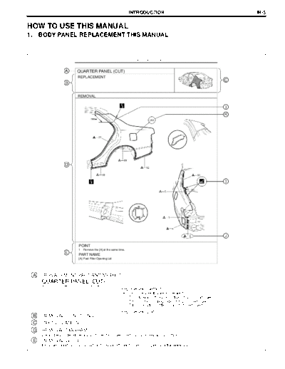
QUARTER PANEL (CUT)
REPLACEMENT
REMOVAL
POINT
1 Remove the [A] at the same time.
PART NAME
[A] Fuel Filler Opening Lid
A : REPLACEMENT PART AND METHOD
QUARTER PANEL (CUT)
Replacement method
(ASSY) ... Assembly replacement
(CUT) ... Major cutting (less than 1 / 2 of part used)
(CUT-H) ... Half cutting (about 1 / 2 of part used)
(CUT-P) ... Partial cutting (most of part used)
Replacement part
B : REMOVAL CONDTIONS
C : PART LOCATION
D : REMOVAL DIAGRAM
Describes in detail removal of the damaged part involving repair by cutting.
E : REMOVAL GUIDE
Provides additional information to more efficiently help you perform the removal.
F13890A
IN-6 INTRODUCTION
BODY PANEL REPLACEMENT BP-35
INSTALLATION
D Temporaily install the new parts and measure each part of the new parts in accordance with the body dimension
diagram. (See the body dimension diagram)
D Inspect the fiting of the related parts around the new parts before welding. This affects the appearance of the F
finish.
D After welding, apply the polyurethane foam to the corresponding parts.
D After welding, apply body sealer and under-coating to the corresponding parts.
D After applying the top coat layer, apply anti-rust agent to the inside of the necked section structural weld spots.
I
J
G
I
5mm
POINT
1 Before temporarily installing the new parts, apply body sealer to the wheel arch.
HINT:
1) Apply body sealer about 5mm (0.20in.) front the flange, avoiding any oozing.
2) Apply sealer evenly, about 3 - 4mm (0.12 - 0.16in.) in diameter. H
3) For other sealing points, refer to section PC.
PART NAME
[A] Fuel Filler Opening Lid [B] Waterproof Rivet
F : INSTALLATION CONDITIONS
G : INSTALLATION DIAGRAM
Describes in detail installation to the new part involving repair by welding and / or
cutting, but excluding painting.
H : INSTALLATIOLN GUIDE
Provides additional information to more efficiently help you perform the installation.
I : SYMBOLS
(See page IN-7)
J : ILLUSTRATION OF WELD POINTS
Weld method and panel position symbols (See page IN-9)
K : PART NAME
F13891A
INTRODUCTION IN-7
2. SYMBOLS
The following symbols are used in the welding diagrams in section BP of this manual to indicate cutting areas
and the types of weld required.
SYMBOLS MEANING ILLUSTRATION
CUT AND JOIN LOCATION
(SAW CUT)
CUT AND JOIN LOCATION
(Cut Location for
Supply Parts)
CUT LOCATION
CUT WITH DISC
SANDER, ETC.
BRAZE
(Removal)
BRAZE
(Installation)
-- WELD POINTS
SPOT WELD OR
-- MIG PLUG WELD
(See Page IN-9)
CONTINUOUS
MIG WELD
(BUTT WELD)
CONTINUOUS
MIG WELD
(TACK WELD)
BODY SEALER
F13893A
IN-8 INTRODUCTION
SYMBOLS MEANING ILLUSTRATION
-- Assembly Mark
BODY SEALER
-- (Flat Finishing)
BODY SEALER
-- (No flat Finishing)
F13894A
INTRODUCTION IN-9
3. ILLUSTRATION OF WELD POINT SYMBOLS
EXAMPLE:
REMOVAL INSTALLATION
Weld points Weld points
Remove weld point and panel position Weld method and panel position
SYMBOLS MEANING ILLUSTRATION SYMBOLS MEANING ILLUSTRATION
Remove
Weld
Spot Weld
Points
(Outside)
MIG Plug
Weld
(Middle)
(Inside)
Spot MIG
Weld
HINT: Panel position symbols are as seen from
the working posture.
F13892A
IN-16 INTRODUCTION
PRECAUTIONS FOR REPAIRING BODY
STRUCTURE PANELS
1. HEAT REPAIR FOR BODY STRUCTURE
PANELS
Toyota prohibits the use of the heat repair method on body
structure panels when repairing a vehicle damaged in a col-
lision.
Panels that have high strength and rigidity, as well as a long
life span for the automobile body are being sought after.
At Toyota, in order to fulfill these requirement, we use high
tensile strength steel sheets and rust preventive steel
sheets on the body.
High tensile steel sheets are made with alloy additives and
a special heat treatment in order to improve the strength.
To prevent the occurrence of rust for a long period of time,
the surface of the steel is coated with a zinc alloy.
If a body structure parts are heat repaired with an acetylene
torch or other heating source, the crystalline organization of
the steel sheet will change and the strength of the steel
sheet will be reduced.
The ability of the body to resist rust is significantly lowered
as well since the rust resistant zinc coating is destroyed by
heat and the steel sheet surface is oxidized.
2. STRUCTURE PANEL KINKS
A sharp deformation angle on the panel that cannot be re-
turned to its original shape by pulling or hammering is
called a kink.
Since structure parts were designed to exhibit a 100% per-
formance when they were in their original shape, if they are
deformed in an accident, or if the deformed parts are re-
paired and reused, they become unable to exhibit the same
performance as intended in the design.
It is necessary to replace the part where the kink has oc-
curred.
INTRODUCTION IN-17
3. IMPACT BEAM REPAIR
The impact beam and bracket are necessary and important
parts in maintaining a survival space for passengers in a
side collision.
For impact beam, we use special high tensile strength
steel.
The high tensile strength steel maintains its special crystal-
line organization by heat treatment or alloy additives.
Since these parts were designed to exhibit a 100% perfor-
mance when they were in their original shape, if they are
deformed in an accident, or if the deformed parts are re-
paired and reused, they become unable to exhibit the same
performance as intended in the design.
It is necessary to replace the door assembly when impact
beam or bracket is damaged.
IN-10 INTRODUCTION
PROPER AND EFFICIENT WORK
PROCEDURES
1. REMOVAL
(a) PRE-REMOVAL MEASURING
(1) Before removal or cutting operations, take measure-
ments in accordance with the dimension diagram. Al-
ways use a puller to straighten a damaged body or
frame.
F10007
(b) CUTTING AREA
Cutting Okay
(1) Always cut in a straight line and avoid reinforced area.
Reinforcement
Corners
F10008A
(c) PRECAUTIONS FOR DRILLING OR CUTTING
(1) Check behind any area to be drilled or cut to insure
that there are no hoses, wires, etc., that may be dam-
aged.
HINT: See "Handling Precautions on Related Compo-
nents" on page IN-15.
WRONG F10009A
(d) REMOVAL OF ADJACENT COMPONENTS
(1) When removing adjacent components, apply protec-
tive tape to the surrounding body and your tools to pre-
vent damage.
HINT: See "Handling Precautions on Related Compo-
nents" on page IN-15.
F10010
INTRODUCTION IN-11
2. PREPARATION FOR INSTALLATION
(a) SPOT WELD POINTS
(1) When welding panels with a combined thickness of
Less than over 3mm (0.12in.), use a MIG (Metal Inert Gas) weld-
3mm
er for plug welding.
HINT: Spot welding will not provide sufficient durability
for panels over 3mm (0.12in.) thick.
F10011A
(b) APPLICATION OF WELD-THROUGH PRIMER
(SPOT SEALER)
(1) Remove the paint from the portion of the new parts
and body to be welded, and apply weld-through prim-
er.
F10012
(c) MAKING HOLES FOR PLUG WELDING
(1) For areas where a spot welder cannot be used, use a
puncher or drill to make holes for plug welding.
REFERENCE: mm (in.)
Thickness of welded portion Size of plug hole
1.0 (0.04) under 5 (0.20) ◦ Jabse Service Manual Search 2026 ◦ Jabse Pravopis ◦ onTap.bg ◦ Other service manual resources online : Fixya ◦ eServiceinfo