Service Manuals, User Guides, Schematic Diagrams or docs for : . Car Manuals Toyota Sienna 1998-2003 Approved FSM 06 cylhea remo

<< Back | Home

Most service manuals and schematics are PDF files, so You will need Adobre Acrobat Reader to view : Acrobat Download Some of the files are DjVu format. Readers and resources available here : DjVu Resources
For the compressed files, most common are zip and rar. Please, extract files with Your favorite compression software ( WinZip, WinRAR ... ) before viewing. If a document has multiple parts, You should download all, before extracting.
Good luck. Repair on Your own risk. Make sure You know what You are doing.


Image preview - the first page of the document
remo


>> Download remo documenatation <<

Text preview - extract from the document
                                                                                               EM-33
                        ENGINE MECHANICAL      -   CYLINDER HEAD
                                                                                                EM0B8-05


                                       REMOVAL
                                       NOTICE:
                                       Do not remove or install the camshaft timing gear (VVT-i)
                                       beside changing VVT-i or the camshaft.
                                       1.   REMOVE OUTER FR COWL TOP PANEL ASSEMBLY
                                            (See page BO-35 )
                                       2.   DRAIN ENGINE COOLANT
                                       3.   REMOVE RH FENDER APRON SEAL
                                       4.   REMOVE GENERATOR DRIVE BELT
                                            (See page CH-7 )
                                       5.   REMOVE PS PUMP (See page SR-24 )
                                       6.   REMOVE FRONT EXHAUST PIPE (See page EM-76 )
                                       7.   REMOVE RH ENGINE MOUNTING STAY


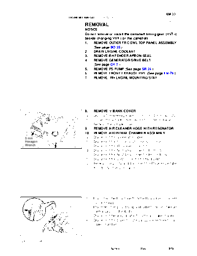
                                       8.    REMOVE V-BANK COVER
                                       (a)   Using a 5 mm hexagon wrench, remove the 3 cap nuts.
                                       (b)   Loosen the V-bank cover fastener counterclockwise.
                                       (c)   Remove the V-bank cover.
                                       9.    REMOVE AIR CLEANER HOSE WITH RESONATOR
                                       10.   REMOVE AIR INTAKE CHAMBER ASSEMBLY
  5 mm                                 (a)   Disconnect the accelerator cable.
  Hexagon                              (b)   Disconnect the throttle position sensor connector.
  Wrench                      A10518   (c)   Disconnect the IAC valve connector.
                                       (d)   Disconnect the No.1 VSV connector for the ACIS.
                                       (e)   Disconnect the No.2 VSV connector for the ACIS.
                                       (f)   Disconnect the VSV connector for the EVAP.
                                       (g)   Remove the 2 nuts, and disconnect the PS pressure tube
                                             from the No.1 engine hanger.


                                       (h)   Disconnect the PCV hose from the PCV valve on the RH
                                             cylinder head.
                                       (i)   Disconnect the ground strap and cable from the intake air
                                             control valve for the ACIS.
                        (h)
                                       (j)   Disconnect the ground cable from the air intake chamber.
                                       (k)   Disconnect the brake booster vacuum hose from the air
                                             intake chamber.
        (j)
                  (i)         A06658


2001 SIENNA (RM787U)

                                                         Author :            Date :             976
EM-34
                                 ENGINE MECHANICAL      -   CYLINDER HEAD

                                                (l)   Disconnect the 2 water bypass hoses from the throttle
                                                      body.
                                                (m)   Disconnect the air assist hose from the throttle body.
                          (l)                   (n)   Disconnect the purge hose from the pipe on the emission
                 (n)
                                       (l)
                                                      control valve set.
   (p)                           (m)            (o)   Disconnect the 2 vacuum hoses from the vacuum tank for
                                                      the ACIS.
                                                (p)   Disconnect the engine wire clamp from the emission con-
                         (o)                          trol valve set.
                                       A15357


                                                (q)   Remove the 2 bolts and No.1 engine hanger.
                                                (r)   Remove the 2 bolts and throttle body bracket.
                Engine
                Hanger

                 Throttle Body
                 Bracket


                                       A09695


                   8 mm Hexagon Wrench          (s)   Using an 8 mm hexagon wrench, remove the 2 bolts, 2
                                                      nuts, the air intake chamber assembly and gasket.


                                       A05073


                                                11. REMOVE INTAKE MANIFOLD ASSEMBLY
                                                (a) Disconnect the 6 injector connectors.
                                                (b) Disconnect the fuel inlet hose from the fuel filter.
                                                CAUTION:
                                                Perform connecting operations of the fuel tube connector
                                                (quick type) after observing the precautions.
                                                (See page SF-1 )
                                                (c) Disconnect the heater hose from the intake manifold.
                   (c)    (b)          A05074


                                                (d) Remove the 9 bolts, 2 nuts, 2 plate washers, the intake
                                                    manifold, delivery pipes and injectors assembly.
                                                NOTICE:
                                                 S  Be careful not to drop the injectors when removing
                                                    the delivery pipes.
                                                 S  Pay attention to put any hung load on the injector to
                                                    and from the side direction.
                                                12. REMOVE WATER OUTLET
                                       A07428   (a) Disconnect the ECT sender gauge connector.
                                                (b) Disconnect the ECT sensor connector.
2001 SIENNA (RM787U)

                                                                  Author :           Date :             977
                                                                                             EM-35
                          ENGINE MECHANICAL   -   CYLINDER HEAD

                                      (c)   Disconnect the ground strap connector.
                                      (d)   Disconnect the upper radiator hose.
                                      (e)   Disconnect the engine coolant reservoir hose.


                                      (f)   Remove the 2 bolts, 2 nuts and 2 plate washers.
                                      (g)   Disconnect the water bypass hose, and remove the water
                                            outlet.
                                      (h)   Remove the 2 gaskets.
                                      13.   REMOVE IGNITION COILS
                                      14.   REMOVE SPARK PLUGS
                                      15.   REMOVE TIMING BELT (See page EM-16 )
                                      16.   REMOVE CAMSHAFT TIMING PULLEYS
           Gasket            P20049         (See page EM-16 )
                                      17.   REMOVE NO.2 IDLER PULLEY (See page EM-16 )
                                      18.   REMOVE NO.3 TIMING BELT COVER
                  Clamp
                                      (a)   Disconnect the 3 engine wire clamps from the timing belt
                           Clamp            cover.
                                      (b)   Remove the 6 bolts and timing belt cover.
                                      19.   REMOVE CAMSHAFT POSITION SENSORS
                                      20.   REMOVE CAMSHAFT TIMING OIL CONTROL VALVES


                          Clamp
                             A05077


                                      21.  DISCONNECT ENGINE WIRE PROTECTOR FROM
                                           REAR SIDE
                                      Remove the nut, and disconnect the engine wire protector from
                                      the RH cylinder head.


                             A10531


                                      22.    DISCONNECT ENGINE WIRE AND PROTECTOR
                                             FROM RH SIDE
                                      Remove the 5 nuts, and disconnect the engine wire and protec-
                                      tor from the RH cylinder head cover.


                             A10519


2001 SIENNA (RM787U)

                                                        Author :           Date :             978
EM-36
                                     ENGINE MECHANICAL   -   CYLINDER HEAD

                                                 23.   DISCONNECT ENGINE WIRE PROTECTOR FROM LH
                                                       SIDE
                                                 Remove the 2 bolts, and disconnect the engine wire protector
                                                 from the LH cylinder head cover.


                                        A05205


                                       Rear      24. DISCONNECT CYLINDER HEAD REAR PLATE FROM
                                       Plate         LH CYLINDER HEAD
                                                 Remove the 2 bolts, and disconnect the rear plate.
                                                 25. DISCONNECT WATER INLET PIPE FROM LH CYL-
                                                     INDER HEAD AND WATER INLET
                                                 (a) Remove the bolt, and disconnect the inlet pipe from the
                                                     water inlet.
                                                 (b) Remove the O-ring from the inlet pipe.
                       Inlet Pipe       A07596


                                                 26. REMOVE PS PUMP BRACKET
                                                 Remove the 3 bolts and pump bracket.


                                        A05189


                                                 27.   REMOVE RH EXHAUST MANIFOLD
                                                 (a)   Disconnect the oxygen sensor (bank 1 sensor 1) connec-
                                                       tor.
                                                 (b)   Remove the 3 bolts and heat insulator.
                                                 (c)   Remove the 6 nuts, exhaust manifold and gasket.


                                        A01813


                                                 28.   REMOVE LH EXHAUST MANIFOLD
                                                 (a)   Disconnect the oxygen sensor (bank 2 sensor 1) connec-
                                                       tor.
                                    Manifold     (b)   Remove the bolt, nut and exhaust manifold stay.
                                    Stay         (c)   Remove the 3 bolts and heat insulator.
                                                 (d)   Remove the 6 nuts, exhaust manifold and gasket.


                                        A07281


2001 SIENNA (RM787U)

                                                                   Author :           Date :            979
                                                                                                         EM-37
                                  ENGINE MECHANICAL     -   CYLINDER HEAD

                                                29.   REMOVE OIL DIPSTICK AND GUIDE
                                                (a)   Remove the bolt holding the dipstick guide to the LH cylin-
                                                      der head.
                                                (b)   Pull out the dipstick guide together with the dipstick from
                                                      the No.1 oil pan.
                                                (c)   Remove the O-ring from the dipstick guide.

                                   O-Ring
                                       A07283


                                                30. REMOVE CYLINDER HEAD COVERS
                                                Remove the 8 bolts, cylinder head cover and gasket. Remove
                                                the 2 cylinder head covers.
                                                31. REMOVE CAMSHAFTS OF RH CYLINDER HEAD
                                                NOTICE:
                                                Since the thrust clearance of the camshaft is small, the
                                                camshaft must be held level while it is being removed. If the
                                                camshaft is not kept level, the portion of the cylinder head
                                       A01816   receiving the shaft thrust may crack or be damaged, caus-
                                                ing the camshaft to seize or break. To avoid this, the follow-
                                                ing steps should be carried out.


Intake                                          (a)   Remove the intake camshaft.
                                                      (1) Align the timing marks (2 dot marks) of the camshaft
                                                          drive and driven gears by turning the camshaft with
                                                          a wrench.


                       Align           A05280


Intake       Main Gear                                (2)   Secure the exhaust camshaft sub-gear to the main
                                Sub-Gear
                                                            gear with a service bolt.
                                                      Recommended service bolt:
                                                      Thread diameter 6 mm
                                                      Thread pitch 1.0 mm
                                                      Bolt length 16 - 20 mm
                                                HINT:
                               Service Bolt     When removing the camshaft, mark certain that the torsional
                                       A05195   spring force of the sub-gear has been eliminated by the above
                                                operation.
2001 SIENNA (RM787U)

                                                                  Author :             Date :              980
EM-38
                                                 ENGINE MECHANICAL            -   CYLINDER HEAD

 Intake                                                                 (3)       Uniformly loosen and remove the 10 bearing cap
                                                 2                                bolts, in several passes, in the sequence shown.
                                            6                           (4)       Remove the 5 bearing caps and intake camshaft.
                                    10                    1
                                                     5
                                             9
                            8

            4                       7
                        3

                                                         A05207


Exhaust                                          1                (b)   Remove the exhaust camshaft.
                                                     2                  (1) Uniformly loosen and remove the 10 bearing cap
                                        5
                                                                             bolts, in several passes, in the sequence shown.
                                9            6
                                                                        (2) Remove the 5 bearing caps, oil seal and exhaust
                    7               10                                       camshaft.
        3
                            8                                     32. REMOVE CAMSHAFTS OF LH CYLINDER HEAD
                4                                                 NOTICE:
                                                                  Since the thrust clearance of the camshaft is small, the
                                                         A05197   camshaft must be held level while it is being removed. If the
                                                                  camshaft is not kept level, the portion of the cylinder head
                                                                  receiving the shaft thrust may crack or be damaged, caus-
                                                                  ing the camshaft to seize or break. To avoid this, the follow-
                                                                  ing steps should be carried out.


Intake                                                            (a)   Remove the intake camshaft.
                                                                        (1) Align the timing marks (1 dot mark) of the camshaft
                                                                            drive and driven gears by turning the camshaft with
                                                                            a wrench.


                        Align                            A05284


 Intake                                                                 (2)   Secure the exhaust camshaft sub-gear to the main
                                            Service Bolt                      gear with a service bolt.
                                                                        Recommended service bolt:
                                                                        Thread diameter 6 mm
                                                                        Thread pitch 1.0 mm
                                                                        Bolt length 16 - 20 mm
                                                                  HINT:
                                                                  When removing the camshaft, make sure that the torsional
 Main Gear              Sub-Gear                         A05198   spring force of the sub-gear has been eliminated by the above
                                                                  operation.
2001 SIENNA (RM787U)

                                                                                        Author :           Date :            981
                                                                                                                             EM-39
                                                   ENGINE MECHANICAL          -   CYLINDER HEAD

Intake                                     1                        (b)     Uniformly loosen and remove the 10 bearing cap bolts, in
                                  5                    2
                                               6                            several passes, in the sequence shown.
                         9
                                                                    (c)     Remove the 5 bearing caps and intake camshaft.
                 7                    10
                         8
     3
             4


                                                           A05199


Exhaust                                            2                (d)     Remove the exhaust camshaft
                                                                            (1) Uniformly loosen and remove the 10 bearing cap
                                           6
                                                             1                  bolts, in several passes, in the sequence shown.
                             10                                             (2) Remove the 5 bearing caps, oil seal and exhaust
                                                   5                            camshaft.
                     7
                                           9                        HINT:
         4                   8                                      S       Arrange the camshafts in the correct order.
                                                                    S       Arrange the bearing caps in the correct order.
                 3                                         A05200


                                                                    33.  DISASSEMBLE EXHAUST CAMSHAFTS
                                                                    (a)  Mount the hexagonal wrench head portion of the cam-
                                                                         shaft in a vise.
                                                                    NOTICE:
                                                                    Be careful not to damage the camshaft.


                                                           P12596


                                                                    (b)     Using SST, turn the sub-gear counterclockwise, and re-
                                                                            move the service bolt.
                                                                            SST 09960-10010 (09962-01000, 09963-00500)


                                 SST
                                                           P12797


                                                                    (c) Using snap ring pliers, remove the snap ring.
                                                                    (d) Remove the wave washer.
                                                                    (e) Remove the camshaft sub-gear.
                                                                    (f)    Remove the camshaft gear spring.
                                                                    HINT:
                                                                    Arrange the camshaft sub-gears and gear springs (RH and LH
                                                                    side).

                                                           P12590


2001 SIENNA (RM787U)

                                                                                        Author :           Date :             982
EM-40
                                         ENGINE MECHANICAL    -   CYLINDER HEAD


                 Recessed Heat Bolt
                                                     34.   REMOVE CYLINDER HEADS
                                                     (a)   Using an 8 mm hexagon wrench, remove the cylinder
                                                           head (recessed head) bolt on each cylinder head, then re-
                                                           peat for the other side, as shown.


         8 mm Hexagon Wrench


 Front


                                            A05222


                                                     (b)   Uniformly loosen and remove the 8 cylinder head (12
                 12 Pointed Head Bolt
                                                           pointed head) bolts on each cylinder head, in several
                                                           passes, in the sequence shown, then repeat for the other
                                                           side, as shown. Remove the 16 cylinder head bolts and
                                                           plate washers.
                                                     NOTICE:
                                                     Head warpage or cracking could result from removing
                                                     bolts in an incorrect order.

         2       7       5       3


         4       6       8       1
Front


◦ Jabse Service Manual Search 2026 ◦ Jabse PravopisonTap.bg ◦ Other service manual resources online : FixyaeServiceinfo