Service Manuals, User Guides, Schematic Diagrams or docs for : . Car Manuals Toyota Sienna 1998-2003 Approved FSM 24 bodypane frontsid
<< Back | HomeMost service manuals and schematics are PDF files, so You will need Adobre Acrobat Reader to view : Acrobat Download Some of the files are DjVu format. Readers and resources available here : DjVu Resources
For the compressed files, most common are zip and rar. Please, extract files with Your favorite compression software ( WinZip, WinRAR ... ) before viewing. If a document has multiple parts, You should download all, before extracting.
Good luck. Repair on Your own risk. Make sure You know what You are doing.
Image preview - the first page of the document
>> Download frontsid documenatation <<
Text preview - extract from the document
RE-20                                           BODY PANEL REPLACEMENT

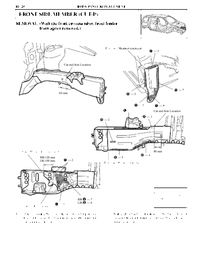
     FRONT SIDE MEMBER (CUT-P)
REMOVAL (With the front crossmember, front fender
        front apron removed.)


                                                             Front Side Member Extension
                                                                                                    --3


                                    Cut and Join Location


                                                                                                                       --7
                                  60 mm                                          --5


                                                                                       --2                --6
                                                                              --6                   Cut and Join Location
                                                                                              --1
                                                             --2


Front Side Member Reinforcement                                                                     80 mm
                                                                                             --4
                   RH:120 mm                                           --5
                   LH:100 mm              --2
                                                             Front Side Member Outer Plate


                                                                                                          mm          in.
                                                                                                           60        2.36
                                                RH:   --7                                                  80        3.15
                                                LH:   --6                                                 100        3.94
                                  --1                                                                     120        4.72
      Cut and Join Location

1.    After removing the front side member outer plate and   2.    Shift each cut and join locations of the front side outer
      front side member extension, remove the front side           member, front side inner member and front side mem-
      member reinforcement.                                        ber reinforcement.
                                             BODY PANEL REPLACEMENT                                                        RE-21
INSTALLATION
                                                                                                 [LH only]

                                                                                        Battery Carrier Support
                                                                                           --2

                                                                                                                          --2

                                                  --2
                                                                                                                          --2


                                                                                        --2                         --2

                   Butt Weld


                                                                                  RH:     --4         RH:     --7
                   Front Body Mounting Reinforcement                              LH:     --5         LH:     --6
                                                  Front Side Member Front Plate                --2
                                   --4
                                                                                  --2
                                                       --8


                                                                                                              --1
                                                                    --3     --4     Butt Weld
                          --2                                 -- 1 Front Suspension Member Mounting Front Bracket
                                         Front Bumper
                                         Mounting Reinforcement                                         --3


                       --6
                                       --1                                         --5


                                                                                                                           --7


                                   --4        Butt Weld                                       --2
                 --5
      --2                                                                                                     --6


1.   Temporarily install the new parts and measure each
     part in accordance with the body dimension diagram.
◦ Jabse Service Manual Search 2026 ◦ Jabse Pravopis ◦ onTap.bg ◦ Other service manual resources online : Fixya ◦ eServiceinfo