Service Manuals, User Guides, Schematic Diagrams or docs for : . Car Manuals Toyota Sienna 1998-2003 Approved FSM 22 systemci 043ea
<< Back | HomeMost service manuals and schematics are PDF files, so You will need Adobre Acrobat Reader to view : Acrobat Download Some of the files are DjVu format. Readers and resources available here : DjVu Resources
For the compressed files, most common are zip and rar. Please, extract files with Your favorite compression software ( WinZip, WinRAR ... ) before viewing. If a document has multiple parts, You should download all, before extracting.
Good luck. Repair on Your own risk. Make sure You know what You are doing.
Image preview - the first page of the document
>> Download 043ea documenatation <<
Text preview - extract from the document
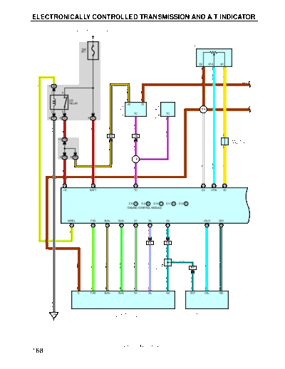
ELECTRONICALLY CONTROLLED TRANSMISSION AND A/T INDICATOR
FROM POWER SOURCE SYSTEM (SEE PAGE 52)
T2
THROTTLE POSITION SENSOR
15A
EFI
E2 VTA VC
2 3 1
L- W
BR
Y
BR
7 2K
Y- G
B- Y
BR
1 5
EFI 12 3
CONNECTOR 1
CONNECTOR 3
RELAY +B E1
BR BR
DATA LINK
DATA LINK
E4
2 3
TC TC
D1
D3
4 2F 2 2J 8 2J 11 13
B- Y
P- B
W- B
B- R
R- B
P- B
12 IH1 18 IH2 B
J12
11 3B JUNCTION
CONNECTOR
B- Y
P- B
B
2 3B 9 3A
I2
L- W
W
Y
B- R
P- B
16 A 1 A 5 B 18 D 23 D 2 D
+B BATT TC E2 VTA1 VC
E 8 A , E 9 B , E10 C , E11 D , E12 E
ENGINE CONTROL MODULE
MREL THO SLN+ SLN- S1 SL S2 IDLO OD1
8 A 13 D 20 E 19 E 7 E 15 C 1 C 25 B 24 B
P- L
L- B
Y- G
5 IH1 11 IH2
L- B
CONNECTOR
D
JUNCTION
D L- B
G- W
W- G
G- Y
B- Y
P- L
B- L
BR
L
J13
D 13 IH1
L- B
L- B
7 2 3 8 5 1 10 6 13 14
E THO SLN+ SLN- S1 SL S2 ECT IDL OD
W- B
E1 C15
EA ELECTRONICALLY CONTROLLED CRUISE CONTROL ECU
TRANSMISSION SOLENOID
2001 SIENNA (EWD420U)
168
FROM POWER SOURCE SYSTEM (SEE PAGE 52)
15A 5A
STOP STARTER
7 1C 3 1J
B- W
W
BR
2
STOP LIGHT SW
BR
S6 1
Y
G- W
4 1R O
R- B
BR
5 1R
B- W
G- W
1
ENGINE COOLANT
TEMP. SENSOR
CONNECTOR
18 3B C
JUNCTION
R- B
J6
BR
2 C
O
Y
E2
6 3B
G- W
B- W
G- B
14 D 15 A 20 B 13 C 14 C 8 C
THW STP NSW L 2 R
E 8 A , E 9 B , E10 C , E11 D , E12 E
ENGINE CONTROL MODULE
NC2- NC2+ E03 E02 E01 E1 ODMS ODLP SPD
23 E 24 E 30 E 31 E 21 E 17 D 12 C 9 A 22 B
W- B
W- B
W- B
G- O
G- R
V- Y
BR
Y
L
18 3C
O/D DIRECT CLUTCH
1
SPEED SENSOR
13 3A
V- Y
A
BR A A BR
O3
2
J14
A JUNCTION
CONNECTOR 3
O/D MAIN SW
V- Y
O2
G- R
BR
1
W- B
EB EC
2001 SIENNA (EWD420U)
169
ELECTRONICALLY CONTROLLED TRANSMISSION AND A/T INDICATOR
FROM POWER SOURCE SYSTEM (SEE PAGE 52) R- L(*2)
7
R- L(*1) R- L
IH1 P1
A/T INDICATOR LIGHT SW
2 [PARK/NEUTRAL POSITION SW]
10A 15A
GAUGE CIG C
2
(PARK/NEUTRAL
POSITION SW)
2 1D 6 1J LL 2L DL NL RL PL
DIODE
4 3 10 9 8 7
D12
GR
1 3
G- W
L- W
B- R
R- B
LG
Y
(*1)
GR
P 5 IH2 6 IH2 7 IH2 8 IH2 4 IH1 10 IH2
(* 1)
A
CONNECTOR
GR A
Y
GR A JUNCTION
J17
(W/ VSC)
CONNECTOR
D
G- W
A
JUNCTION
Y Y D
L- W
R- B
B- R
LG
J7
D
O O
CONNECTOR
JUNCTION
B
R- B R- B B
J7
CONNECTOR
D
B
JUNCTION
CONNECTOR
D
(W/O VSC)
12 3C 3 3C 3 3D 13 3B
JUNCTION
GR
J17
D
J18
D
4 3B
13 3C 12 3D
GR
G- W
L- W
B- R
R- B
LG
Y
(W/ VSC)
C10 A , C11 C
COMBINATION METER 9 A 6 A 5 A 7 A 4 A 3 A 2 A
O/D OFF
SPEEDOMETER
D
N
R
P
L
2
12 A 16 A 11 A 8 A 6 C
(W/O VSC)
(W/ VSC)
LG- B
W- B
G- R
L- O
V- Y
BR
* 1 : W/ WIRELESS DOOR LOCK CONTROL
* 2 : W/O WIRELESS DOOR LOCK CONTROL
4 ID1
TRANSLATE ECU
ACTUATOR
FROM ABS
AND ECU
W- B
FROM
A A A A B A
BR
J2 A , J3 B
JUNCTION
CONNECTOR
V- Y
W- B
B B
G- R
W- B
W- B
BR
IH IJ ED
2001 SIENNA (EWD420U)
170
SYSTEM OUTLINE
Previous automatic transaxle have selected each gear shift using the mechanically controlled throttle hydraulic pressure,
governor hydraulic pressure and lock-up hydraulic pressure. The electronically controlled transmission, however, electrically
controls the line pressure and lock-up pressure etc., through the solenoid valve. Engine control module control of the
solenoid valve based on the input signals from each sensor, makes smooth driving possible by shift selection for each gear
which is most appropriate to the driving conditions at that time.
1. GEAR SHIFT OPERATION
During driving, the engine control module selects the shift for each gear which is most appropriate to the driving conditions,
based on input signals from the engine coolant temp. sensor to TERMINAL THW of the engine control module, and also the
input signals to TERMINAL SPD of the engine control module from the speedometer. Current is then output to the
electronically controlled transmission solenoid. When shifting to 1st speed, current flows from TERMINAL S1 of the engine
control module to TERMINAL 3 of the electronically controlled transmission solenoid to GROUND, and continuity to the no. 1
solenoid causes the shift.
For the 2nd speed, current flows from TERMINAL S1 of the engine control module to TERMINAL 3 of the electronically
controlled transmission solenoid to GROUND, and from TERMINAL S2 of the engine control module to TERMINAL 1 of the
electronically controlled transmission solenoid to GROUND, and continuity to solenoids no. 1 and no. 2 causes the shift.
For the 3rd speed, there is no continuity to no. 1 solenoid, only to no. 2, causing the shift.
Shifting into 4th speed (Overdrive) takes place when there is no continuity to both no. 1 and no. 2 solenoid.
2. LOCK-UP OPERATION
When the engine control module judges from each signal that lock-up operation conditions have been met, current flows
from TERMINAL SL of the engine control module to TERMINAL 2 of the electronically controlled transmission solenoid to
GROUND, and continuity to the lock-up solenoid performs the lock-up operation.
3. STOP LIGHT SW CIRCUIT
If the brake pedal is depressed (Stop light SW on) when driving in lock-up condition, a signal is input to TERMINAL STP of
the engine control module, the engine control module operates, and continuity to the lock-up solenoid is cut.
4. OVERDRIVE CIRCUIT
O/D main SW on
When the O/D main SW is turned on, a signal is input into TERMINAL ODMS of the engine control module and engine
control module operation causes gear shift when the conditions for overdrive are met.
O/D main SW off
When the O/D main SW is turned off, a signal is input into TERMINAL ODMS of the engine control module, and turns on
the O/D off indicator light. This activates the ECU, and the transmission system is controlled not to shift to overdrive.
SERVICE HINTS
E8 (A), E9 (B), E11 (D), E12 (E) ENGINE CONTROL MODULE
S1,S2-E1 : 9.0- 14.0 volts with the solenoid on
0- 1.5 volts with the solenoid off
L-E1 : 7.5- 14.0 volts with the shift lever at L position
2-E1 : 7.5- 14.0 volts with the shift lever at 2 position
R-E1 : 7.5- 14.0 volts with the shift lever at R position
STP-E1 : 7.5- 14.0 volts with the brake pedal depressed
THW-E2 : 0.2- 1.0 volts with the engine coolant temp. 80◦ Jabse Service Manual Search 2026 ◦ Jabse Pravopis ◦ onTap.bg ◦ Other service manual resources online : Fixya ◦ eServiceinfo