Service Manuals, User Guides, Schematic Diagrams or docs for : . Car Manuals Toyota Sienna 1998-2003 Approved FSM 22 systemci 045abs
<< Back | HomeMost service manuals and schematics are PDF files, so You will need Adobre Acrobat Reader to view : Acrobat Download Some of the files are DjVu format. Readers and resources available here : DjVu Resources
For the compressed files, most common are zip and rar. Please, extract files with Your favorite compression software ( WinZip, WinRAR ... ) before viewing. If a document has multiple parts, You should download all, before extracting.
Good luck. Repair on Your own risk. Make sure You know what You are doing.
Image preview - the first page of the document
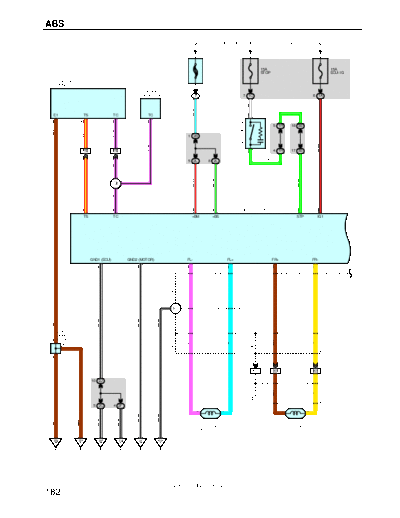
>> Download 045abs documenatation <<
Text preview - extract from the document
ABS
FROM POWER SOURCE SYSTEM (SEE PAGE 52)
1
60A 15A 15A
ABS STOP ECU- IG
D1
DATA LINK
CONNECTOR 1 2
D3
DATA LINK
CONNECTOR 3 7 7 1C 6 1A
W
G- W
W- L
E1 TS TC TC 2
3 16 11 13
STOP LIGHT SW
5 1R 18 3B
R- Y
P- B
BR
1 2B
S6
B- R
P- B
17 IH2 18 IH2 1 4 1R 17 3B
5 2L 6 2L G- W
P- B
G- W
W- G
W- R
R- Y
I2
P- B
A5
6 14 24 9 ABS ACTUATOR AND ECU 5 15
TS TC +BM +BS STP IG1
GND1 (ECU) GND2 (MOTOR) FL- FL+ FR+ FR-
8 23 19 20 22 21
(SHIELDED)
(SHIELDED)
E2
W- B
W- B
W- B
BR
J14
(SHIELDED)
(SHIELDED)
JUNCTION
A CONNECTOR
BR
P
Y
L
A
A
4 IK5 7 IK5 3 IK5
10 2J
(SHIELDED)
BR
Y
5 2C 4 2F
2 1 1 2
W- B
W- B
W- B
W- B
A6 A7
BR
BR
ABS SPEED SENSOR ABS SPEED SENSOR
FRONT LH FRONT RH
EB EC EE EA IG ED
2001 SIENNA (EWD420U)
182
FROM POWER SOURCE SYSTEM (SEE PAGE 52)
GR * 1 : W/ WIRELESS DOOR LOCK CONTROL
* 2 : W/O WIRELESS DOOR LOCK CONTROL
15A 10A C10 A , C11 C
CIG GAUGE
9 A COMBINATION METER
D12
DIODE
ABS
6 1J (PARK/NEUTRAL 2 1D
POSITION SW) J17
GR
P 1 3 GR
TIRE PRESSURE
SPEEDOMETER
JUNCTION
A CONNECTOR
(*1) (*1)
A A GR
2
R- L
(* 1)
10
PL 7 G- W
7 IH2
R- L 2 C
IH1 9 LG
R- L
G- W
NL
(* 2)
P1 8 IH2
PARK/NEUTRAL 13 3B 5 C 6 C 10 C 12 A 16 A
POSITION SW
LG
V
CONNECTOR
D
JUNCTION
LG- B
W- B
11 3A
GR
BR
J17
D
G- W
LG
A5
ABS ACTUATOR AND ECU 1 2 13 11 7
N P WA WTIR SPO
RR+ RR- RL- RL+ INIT
18 17 10 16 12
(SHIELDED)
(SHIELDED)
W
G
R
B
GR- B
TIRE PRESSURE WARNING
2 IC2 10 IC2 11 IC2 3 IC2 9 IC2 2
STANDARDIZATION SW
B6
(SHIELDED)
(SHIELDED)
BR
1
W
G
R
B
BR- W
BR- W
T6
W- B
W- B
8 BA2 9 BA2 6 BA2 2 BA2 7 BA2 10 BA2 4 ID1
(SHIELDED)
J3 B
(SHIELDED) B A
W
CONNECTOR
B
3 1M
JUNCTION
J2 A ,
G
R
B B
2 1 1 2 8 1J
W- B
W- B
A18 A17
BR
ABS SPEED SENSOR ABS SPEED SENSOR
REAR RH REAR LH
IJ ED IH
2001 SIENNA (EWD420U)
183
ABS
SYSTEM OUTLINE
ABS system controls the respective brake fluid pressures acting on the disc brake cylinders of the right front wheel, left front
wheel and rear wheels when the brakes are applied in a panic stop, so that the wheels do not lock. This results in improved
directional stability and steerability during panic braking.
Tire pressure warning system turns on the tire pressure warning light and warns the driver of low tire pressure, when driving
with a low tire pressure, which may cause trouble driving.
However, this system can detect the low tire pressure condition only if one of the tires has such a condition in particular
compared to other tires, and it cannot detect. Therefore, it can not detect natural (Gradual) air loss occurring to the tires.
1. INPUT SIGNALS
(1) Speed sensor signal
The speed of the wheels is detected and input to TERMINALS FL+, FR+, RL+ and RR+ of the ABS actuator and ECU.
(2) Stop light SW signal
A signal is input to TERMINAL STP of the ABS actuator and ECU when the brake pedal is operated.
(3) Standardization SW Signal
A signal is input to TERMINAL INIT of the ABS actuator and ECU when the tire pressure warning standardization SW in
operated.
(4) Parking position signal
A signal is input to TERMINAL P of the ABS actuator and ECU when the Shift lever at "P" position.
(5) Neutral position signal
A signal is input to TERMINAL N of the ABS actuator and ECU when the Shift lever at "N" position.
2. ABS SYSTEM OPERATION
During sudden braking the ABS actuator and ECU has signals input from each sensor, which controls the current to the
solenoid inside the actuator and lets the hydraulic pressure acting on each wheel cylinder escape to the reservoir. The pump
inside the actuator is also operating at this time, and it returns the brake fluid from the reservoir to the master cylinder, thus
preventing locking of the vehicle wheels.
If the ABS actuator and ECU judges that the hydraulic pressure acting on the wheel cylinder is insufficient, the current on the
solenoid is controlled and the hydraulic pressure is increased. Holding of the hydraulic pressure is also controlled by the
ABS actuator and ECU, by the same method as above. Pressure reduction, holding and increase are repeated to maintain
vehicle stability and to improve steerability during sudden braking.
3. OPERATION OF TIRE PRESSURE WARNING SYSTEM
In accordance with the reduction of tire pressure, tire diameter becomes small and the tire rotation speed becomes greater.
In the relation between the difference of the vehicle speed of normal wheels and the low pressure wheel and the tire
pressure, based on the speed signal detected during driving, it detects the change of the tire pressure.
As a result, if the system judges that the tire pressure has reduced, it turns on the tire pressure warning light and warn the
driver using the signal from the ABS actuator and ECU.
SERVICE HINTS
A6, A7 ABS SPEED SENSOR FRONT LH, RH
2-1 : Approx. 1.6 k
A17, A18 ABS SPEED SENSOR REAR LH, RH
2-1 : Approx. 1.1 k
A5 ABS ACTUATOR AND ECU
(Disconnect the ABS actuator and ECU connectors)
14-GROUND : Approx. 12 volts with the ignition SW at ON position and the data link connector 1
TC-E1 not connected
6-GROUND : Approx. 12 volts with the ignition SW at ON position and the data link connector 1
TS-E1 not connected
8,23-GROUND : Always continuity
15-GROUND : Approx. 12 volts with the ignition SW at ON position
5-GROUND : Approx. 12 volts with the brake pedal depressed
9,24-GROUND : Always approx. 12 volts
2001 SIENNA (EWD420U)
184
: PARTS LOCATION
Code See Page Code See Page Code See Page
A5 32 C11 C 34 J14 35
A6 32 D1 32 J17 35
A7 32 D3 34 P1 33
A17 36 D12 34 S6 35
A18 36 J2 A 35 T6 35
C10 A 34 J3 B 35
: RELAY BLOCKS
Code See Page Relay Blocks (Relay Block Location)
7 29 R/B No.7 (Engine Compartment Left)
,,, : JUNCTION BLOCK AND WIRE HARNESS CONNECTOR
,,,
,,,
Code See Page Junction Block and Wire Harness (Connector Location)
1A
1C
1D
22 Cowl Wire and Driver Side J/B No.1 (Lower Finish Panel)
No 1
1J
1M
1R
2B
2C 24 g
Engine Room Main Wire and Engine Room J/B No.2 ( g
g (Engine Compartment Left)
)
2F
2J
24 Cowl Wire and Engine Room J/B No 2 (Engine Compartment Left)
No.2
2L
3A
26 Cowl Wire and J/B No 3 (Behind the Combination Meter)
No.3
3B
: CONNECTOR JOINING WIRE HARNESS AND WIRE HARNESS
Code See Page Joining Wire Harness and Wire Harness (Connector Location)
IC2 42 Cowl Wire and Floor Wire (Left Cowl Side Panel)
ID1 42 Instrument Panel Wire and Cowl Wire (The Back Side of the Lower Finish Panel)
IH1
44 Engine Wire and Cowl Wire (Front Side of the Blower Motor)
IH2
IK5 44 Engine Room Main Wire and Cowl Wire (Right Cowl Side Panel)
BA2 46 Gauge Wire and Floor Wire (On the Left Rear Wheel House)
: GROUND POINTS
Code See Page Ground Points Location
EA 40 Front Side of the Right Fender Apron
EB 40 Right Side of the Surge Tank
EC 40 Rear Side of the Surge Tank
ED 40 Near the Left Front Suspension Support
EE 40 Front Side of the Left Fender Apron
IG 42 Left Cowl Side Panel
IH 42 Right Instrument Panel Brace
IJ 42 Right Cowl Side Panel
: SPLICE POINTS
Code See Page Wire Harness with Splice Points Code See Page Wire Harness with Splice Points
E2 40 B6 46 Floor Wire
Cowl Wire
I2 44
2001 SIENNA (EWD420U)
185
◦ Jabse Service Manual Search 2026 ◦ Jabse Pravopis ◦ onTap.bg ◦ Other service manual resources online : Fixya ◦ eServiceinfo