Service Manuals, User Guides, Schematic Diagrams or docs for : . Car Manuals Toyota Sienna 1998-2003 Approved FSM 22 systemci 053rfcft
<< Back | HomeMost service manuals and schematics are PDF files, so You will need Adobre Acrobat Reader to view : Acrobat Download Some of the files are DjVu format. Readers and resources available here : DjVu Resources
For the compressed files, most common are zip and rar. Please, extract files with Your favorite compression software ( WinZip, WinRAR ... ) before viewing. If a document has multiple parts, You should download all, before extracting.
Good luck. Repair on Your own risk. Make sure You know what You are doing.
Image preview - the first page of the document
>> Download 053rfcft documenatation <<
Text preview - extract from the document
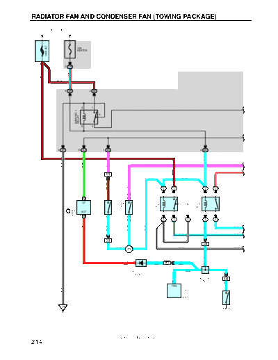
RADIATOR FAN AND CONDENSER FAN (TOWING PACKAGE)
FROM POWER SOURCE SYSTEM (SEE PAGE 52)
1
140A ALT
FUSIBLE LINK
10A
HEATER
BLOCK
F8
3
2 1W
B- R
R- L
B- R
6 2K 2 2B
3 1
MAIN NO. 1
4
RELAY
5 2
4 2F 13 2J 1 2C 2 2C
L- W
P
G- W
W- B
P
W- R
B- R
1 EC1
L- W
BR- B
P
1 1 1 1
3 (* 1) 5 1 1 3
WATER TEMP. SW
ENGINE CONTROL
MAIN NO. 2
PRESSURE SW
26 B 1 2 (* 2)
FAN NO. 3
4
A/C SINGLE
RELAY
CF
RELAY
MODULE
E9 B
ACT
A3
NO. 1
3 2 2 5
W3
6 B 2 2 (* 1)
3 (* 2) 1 1 1 1 1
L- W
R- W
L- W
L- W
L- W
(* 1)
L
L- B L- B
2 EC1 W- B
5 EB1
L- W W- B W- B
I12
L
21
R- W 2 1 L L
IK3 C
(* 1) (*1) (*1)
D23 L C C L
DIODE (* 2)
(MAGNETIC CLUTCH)
J8
JUNCTION 14 IH2
13 CONNECTOR
A/C AMPLIFIER
L
FAN
1
W- B
WATER TEMP.
SW NO. 2
A8
W4
EA
2001 SIENNA (EWD420U)
214
* 1 : AUTOMATIC AIR CONDITIONING
* 2 : MANUAL AIR CONDITIONING
W
2 2H
2 1
40A 40A
CDS RDI
1 2
4
SHORT PIN
W
3
2
A1
M A/C CONDENSER
1 2H 1 2G 2 2F FAN MOTOR
1
L- B
P
L
P R
W- R
P
W- R
1 1 1 1 1
1 5 1 3
FAN NO. 1
FAN NO. 2
4
RELAY
RELAY
2 3 2 5
1 1 1 1
L- W
L- W
L- B
E3
BR
BR
W- B W- B
W- B
L- W
13 IK3
2
R1
J14 M RADIATOR
JUNCTION FAN MOTOR
CONNECTOR
22 1
BR A A BR BR
IH2
W- B
A
W- B
BR
EC EB EE
2001 SIENNA (EWD420U)
215
RADIATOR FAN AND CONDENSER FAN (TOWING PACKAGE)
SYSTEM OUTLINE
FAN MOTOR OPERATION
With the ignition SW turned on, the current through the HEATER fuse flows to the main no.1 relay (Coil side), FAN NO. 3
relay (Coil side), TERMINAL 2 (Automatic air conditioning), 3 (Manual air conditioning) of the A/C single pressure SW,
TERMINAL 2 of the water temp. SW no. 1 and MAIN NO. 2 relay (Coil side).
1. LOW SPEED OPERATION
Only when the A/C system is activated or the water temp. SW no. 2 is turned on, the A/C condenser fan motor and the
radiator fan motor rotates at low speed.
When the A/C system is activated, the current from HEATER fuse flows to the FAN NO. 3 relay (Coil side) to TERMINAL (B)
6 of the engine control module (Automatic air conditioning) or TERMINAL 13 of the A/C amplifier (Manual air conditioning),
causing the FAN NO. 3 relay to turn on. As a result, the current through the CDS fuse flows to TERMINAL 2 of the A/C
condenser fan motor to TERMINAL 1 to TERMINAL 3 of the FAN NO. 2 relay to TERMINAL 4 to TERMINAL 3 of the FAN
NO. 3 relay to TERMINAL 5 to TERMINAL 2 of the radiator fan motor to TERMINAL 1 to GROUND. As the current flows to
the motors in series, the motors rotate at low speed.
When the water temp. SW no. 2 is turned on, the current from HEATER fuse flows to the FAN NO. 3 relay (Coil side) to
TERMINAL 1 of the water temp. SW no. 2 to GROUND, causing the FAN NO. 3 relay to turn on. As a result, the current
through the CDS fuse flows through the same route as above, rotating the motors at low speed.
2. HIGH SPEED OPERATION
Only when the A/C single pressure SW is turned on or the water temp. SW no. 1 is turned on, the A/C condenser fan motor
and the radiator fan motor rotate at high speed.
When the A/C single pressure SW is turned on or the water temp. SW no. 1 is turned on, the current from the RDI fuse flows
to the FAN NO. 1 relay (Point side) to TERMINAL 2 of the radiator fan motor to TERMINAL 1 to GROUND. At the same time,
the current from the CDS fuse flows to TERMINAL 2 of the A/C condenser fan motor to TERMINAL 1 to TERMINAL 3 of the
FAN NO.2 relay to TERMINAL 5 to GROUND.
As the current to the motors flow in parallel as above, the motors rotate at high speed.
SERVICE HINTS
A3 A/C SINGLE PRESSURE SW
3-2 : Open above approx. 15.5 kgf/cm2 (224 psi, 1520 kpa)
Closed below approx. 12.5 kgf/cm2 (181 psi, 1225 kpa)
W3 WATER TEMP. SW NO.1
2-1 : Closed above approx. 95◦ Jabse Service Manual Search 2026 ◦ Jabse Pravopis ◦ onTap.bg ◦ Other service manual resources online : Fixya ◦ eServiceinfo