Service Manuals, User Guides, Schematic Diagrams or docs for : . Car Manuals Toyota Sienna 1998-2003 Approved FSM 22 systemci 054rfcf
<< Back | HomeMost service manuals and schematics are PDF files, so You will need Adobre Acrobat Reader to view : Acrobat Download Some of the files are DjVu format. Readers and resources available here : DjVu Resources
For the compressed files, most common are zip and rar. Please, extract files with Your favorite compression software ( WinZip, WinRAR ... ) before viewing. If a document has multiple parts, You should download all, before extracting.
Good luck. Repair on Your own risk. Make sure You know what You are doing.
Image preview - the first page of the document
>> Download 054rfcf documenatation <<
Text preview - extract from the document
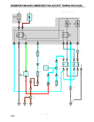
RADIATOR FAN AND CONDENSER FAN (EXCEPT TOWING PACKAGE)
FROM POWER SOURCE SYSTEM (SEE PAGE 52)
* 1 : AUTOMATIC AIR CONDITIONING
* 2 : MANUAL AIR CONDITIONING
1
F8
140A ALT
10A FUSIBLE LINK
HEATER BLOCK
1 1
3
2 1W B- R
30A 30A
RDI CDS
R- L
6 2K 2 2B 2 2
5 1 1 4
MAIN NO. 1
4 FAN
RELAY
NO. 1
RELAY
3 2 2 3
2 2C 4 2F 13 2J 1 2C 2 2F 7 2G 1 2G 2 2H
G- W
W- B
L- W
L- B
L- B
W
A/C CONDENSER
2
FAN MOTOR
2 (*1)
PRESSURE SW
3 (*2)
M
A/C SINGLE
A1
1
L
A3
L- R
L- B
R
L
3 (*1)
2 (*2)
1 1 1 1
L- W
FAN NO. 3 RELAY
FAN NO. 2 RELAY
5 EB1 2 5 2 3
2 EC1 A8 4
L
A/C AMPLIFIER
CONNECTOR
C
JUNCTION
13 L C
G- W
L- W
FAN 1 3 1 5
(* 2)
1 1 1 1 1
J8
C
ENGINE CONTROL
26 B 2
WATER TEMP.
CF L
L
SW NO. 1
W- R
W- R
W- B
L- W
L- W
(* 1)
MODULE
E9 B
W3
ACT 21 IK3 14 IH2
6 B 1
L- W
(* 1)
BR- B
WATER TEMP. SW NO. 2
L
L
(MAGNETIC CLUTCH)
1
R- W
(*1)
BR- B
13 IK3 1
1 EC1
RADIATOR FAN MOTOR
BR
DIODE
2
D23
2
W4
M
R- W
22 IH2
(*1)
1
R1
BR
A
W- B
A J14
JUNCTION
CONNECTOR
W- B
A
W- B
BR
BR
EA EC EB EE
2001 SIENNA (EWD420U)
218
SYSTEM OUTLINE
FAN MOTOR OPERATION
With the ignition SW turned on, the current through the HEATER fuse flows to the FAN NO. 1 relay (Coil side), FAN NO. 2
relay (Coil side) and FAN NO. 3 relay (Coil side). Furthermore, the current through the FAN NO. 1 relay (Coil side) or the FAN
NO. 2 relay (Coil side) flows to TERMINAL 3 of the A/C single pressure SW to TERMINAL 2 to TERMINAL 2 of the water
temp. SW no. 1 to TERMINAL 1 to GROUND, causing the FAN NO. 1 relay to turn off and the FAN NO. 2 relay to turn on.
1. LOW SPEED OPERATION
Only when the A/C system is activated or the water temp. SW no. 2 is turned on, the A/C condenser fan motor and the
radiator fan motor rotates at low speed.
When the A/C system is activated, the current from HEATER fuse flows to the FAN NO. 3 relay (Coil side) to TERMINAL (B)
6 of the engine control module (Automatic air conditionig) TERMINAL 13 of the A/C amplifier (Manual air conditioning),
causing the FAN NO. 3 relay to turn on. As a result, the current through the CDS fuse flows to TERMINAL 2 of the A/C
condenser fan motor to TERMINAL 1 to TERMINAL 3 of the FAN NO. 2 relay to TERMINAL 5 to TERMINAL 3 of the FAN
NO. 3 relay to TERMINAL 5 to TERMINAL 2 of the radiator fan motor to TERMINAL 1 to GROUND. As the current flows in
series to the motors, the motors rotate at low speed.
When the water temp. SW no. 2 is turned on, the current from HEATER fuse flows to the FAN NO. 3 relay (Coil side) to
TERMINAL 1 of the water temp. SW no. 2 to GROUND, causing the FAN NO. 3 relay to turn on. As a result, the current
through the CDS fuse flows the same route as above, rotating the motors at low speed.
2. HIGH SPEED OPERATION
Only when the A/C single pressure SW is turned off or the water temp. SW no. 1 is turned off, the A/C condenser fan motor
and the radiator fan motor rotate at high speed.
When the A/C single pressure SW is turned off, the current from the RDI fuse flows to the FAN NO. 1 relay (Point side) to
TERMINAL 2 of the radiator fan motor to TERMINAL 1 to GROUND. At the same time, the current from the CDS fuse flows
to TERMINAL 2 of the A/C condenser fan motor to TERMINAL 1 to TERMINAL 3 of the FAN NO.2 relay to TERMINAL 4 to
GROUND.
As the current flows in parallel to the motors, the motors rotate at high speed.
SERVICE HINTS
A3 A/C SINGLE PRESSURE SW
3-2 : Open above approx. 15.5 kgf/cm2 (224 psi, 1520 kpa)
Closed below approx. 12.5 kgf/cm2 (181 psi, 1225 kpa)
W3 WATER TEMP. SW NO.1
2-1 : Open above approx. 95◦ Jabse Service Manual Search 2026 ◦ Jabse Pravopis ◦ onTap.bg ◦ Other service manual resources online : Fixya ◦ eServiceinfo