Service Manuals, User Guides, Schematic Diagrams or docs for : . Car Manuals Toyota Sienna 1998-2003 Approved FSM 22 systemci 058macre
<< Back | HomeMost service manuals and schematics are PDF files, so You will need Adobre Acrobat Reader to view : Acrobat Download Some of the files are DjVu format. Readers and resources available here : DjVu Resources
For the compressed files, most common are zip and rar. Please, extract files with Your favorite compression software ( WinZip, WinRAR ... ) before viewing. If a document has multiple parts, You should download all, before extracting.
Good luck. Repair on Your own risk. Make sure You know what You are doing.
Image preview - the first page of the document
>> Download 058macre documenatation <<
Text preview - extract from the document
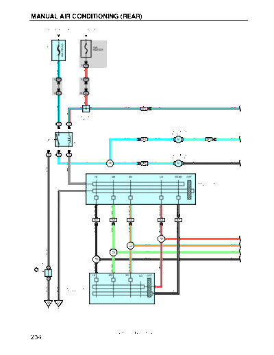
MANUAL AIR CONDITIONING (REAR)
FROM POWER SOURCE SYSTEM (SEE PAGE 52)
40A RR A/C
FUSIBLE LINK
10A
HEATER
BLOCK
F8
5
3 1R
R- L
L- B
1 2D 9 3C
1 2L 20 3C
R- L
B
4
B B R- L R- L R- L
L- B
IC1
R- L
J8
JUNCTION
CONNECTOR
5 5
REAR HEATER RELAY
B12
1 3 BLOWER MOTOR
(REAR HEATER)
2 8
4 L- W L- W 2 1 L- Y L- Y
II4 M BE1
2 5
B11
5 5 5 BLOWER MOTOR
(REAR COOLING)
3
L- W L- W L- W 1 2 B- W B- W
I5 IE1 M
W- B
GR
HI M2 M1 LO REAR OFF
6 H8
HEATER BLOWER SW
(FRONT)
W- B 8
3 7 2 5 1
B- W
GR- R
B- W
L- O
LG
10 IC1 2 IC1 1 IC1 11 IC1 2 IE1
GR- R
B- W
B- W
L- O
LG
GR- R GR- R
B2
L- O L- O
B2
LG LG
W- B
B2
B- W B- W
B3
CONNECTOR
GR- R
B- W
L- O
LG
JUNCTION
B B
J3 B
5 8 4
HI M2 M1 LO OFF
B B
H10 3
W- B
W- B
HEATER BLOWER
SW (REAR) 1 B- W
ED IJ
2001 SIENNA (EWD420U)
234
4
4 B- R B- R B- R B- R 4
B13 BE1
BLOWER RESISTOR (REAR COOLING)
B- R
10
2 L- B W- G W- G 2
BE1
5
3 L- R W- R W- R 3
BE1
B14
1
1 W- L W- L 1
BE1
B15
L- W
B- R
BLOWER RESISTOR
R- L R- L (REAR HEATER)
R- L R- L
B12
R- L R- L
B- R
B13
L- Y
W- G
W- R
L- W
W- L
B- R
L- R
R- L
R- L
R- L
R- L
L- B
L- Y
B- W
B- R
R- L
3 3 3 3 3 3 3 3 3 3 3 3
2 5 2 5 2 5 5 2 5 2
REAR LO RELAY
REAR M1 RELAY
REAR M2 RELAY
REAR RELAY
REAR HI RELAY
4 4 4 4
R12
1 3 1 3 1 3 3 1 3 1
3 3 3 3 3 3 3 3
GR- R
B- W
B- W
W- B
Y- B
Y- B
Y- B
Y- B
L- O
LG
Y- B
GR- R
L- O
LG
B- W
W- B
BM
2001 SIENNA (EWD420U)
235
MANUAL AIR CONDITIONING (REAR)
FROM POWER SOURCE SYSTEM (SEE PAGE 52)
Y- G
6
5
50A HTR
FUSIBLE LINK
2
OFF OFF
BLOCK
F8
ON ON 5A
A/C 6
A/C SW MODE SW
1
B
5
B- R
1 IK7
4
FRONT HEATER RELAY
3 2
B
4
4 5 A10 5 1
A/C SW
R- G
R- B
4 4
A8 A , A9 B
A/C AMPLIFIER 12 A 10 A B
LED F- A/C
W- B
R- HVR SG2 A/MP S5 MHOT MCOOL GND
7 B 4 B 5 B 6 B 3 B 8 B 6 A
W- B
Y- G
Y- R
B- Y
Y- B
B
Y
15 II2 12 II2 14 II2 13 II2 4 II2
Y- G
Y- R
Y- B
B
Y
3 5 1 2 W- B
W- B
J3 B
HOT B A A A A A
CONNECTOR
JUNCTION
J2 A ,
M
COOL
B B
Y- B
4 S7
B- R
SERVO MOTOR
B
B
19 IC2 7 BE1
Y- B
B- Y
B
3 6 5
W- B
W- B
4
V7
W- B
VOLUME SW
BK ED IJ
2001 SIENNA (EWD420U)
236
SYSTEM OUTLINE
1. BLOWER MOTOR (REAR HEATER) OPERATION
Current is applied at all times through the RR A/C fuse to TERMINAL 1 of the rear heater relay.
When the ignition SW is turned on, the current flows through HEATER fuse to TERMINAL 3 of the rear heater relay to
TERMINAL 5 to TERMINAL 6 of the heater blower SW (Front), rear HI relay (Coil side), rear LO relay (Coil side), rear M1
relay (Coil side), rear M2 relay (Coil side) and rear relay (Coil side).
(1) Heater blower SW (Front) operation
Low speed operation
When the blower SW is moved to LO position, the current to TERMINAL 6 of the heater blower SW (Front) flows to
TERMINAL 8 to GROUND, causing the rear heater relay to turn on. This causes the current to flow through the rear
heater relay (Point Side) to TERMINAL 2 of the blower motor (Rear heater) to TERMINAL 1 to TERMINAL 4 of the rear
relay to TERMINAL 2 to TERMINAL 4 of the blower resistor (Rear heater) to TERMINAL 1 to TERMINAL 4 of the rear
LO relay to TERMINAL 3 to TERMINAL 5 of the heater blower SW (Front) to TERMINAL 8 to GROUND, rotating the
blower motor at low speed.
Medium speed operation (Operation at M1, M2)
When the blower SW is moved to M1 position, the current to TERMINAL 6 of the heater blower SW (Front) flows to
TERMINAL 8 to GROUND, causing the rear heater relay to turn on. This causes the current to flow through the rear
heater relay (Point Side) to TERMINAL 2 of the blower motor (Rear heater) to TERMINAL 1 to TERMINAL 4 of the rear
relay to TERMINAL 2 to TERMINAL 4 of the blower resistor (Rear heater) to TERMINAL 3 to TERMINAL 4 of the rear
M1 relay to TERMINAL 3 to TERMINAL 2 of the heater blower SW (Front) to TERMINAL 8 to GROUND. At this time, the
blower resistance of the blower resistor (Rear heater) is smaller than at low speed, so the blower motor rotates at
medium low speed.
When the blower SW is moved to M2 position, the current through the motor flows from TERMINAL 4 of the blower
resistor (Rear heater) to TERMINAL 2 to TERMINAL 4 of the rear M2 relay to TERMINAL 3 to TERMINAL 7 of the
heater blower SW (Front) to TERMINAL 8 to GROUND. At this time, resistance of the blower resistor (Rear heater) is
smaller than at M1 position, so the blower motor rotates at medium high speed.
High speed operation
When the blower SW is moved to HI position, the current to TERMINAL 6 of the heater blower SW (Front) flows to
TERMINAL 8 to GROUND, causing the rear heater relay to turn on. At this time, the current flows to TERMINAL 3 of the
heater blower SW (Front) to TERMINAL 8 to GROUND, causes the rear HI relay to turn on.
This causes the current to flow through the rear heater relay (Point Side) to TERMINAL 2 of the blower motor (Rear
heater) to TERMINAL 1 to TERMINAL 4 of the rear relay to TERMINAL 2 to TERMINAL 2 of the rear HI relay to
TERMINAL 1 to GROUND, rotating the blower motor at high speed.
(2) Heater blower SW (Rear) operation
With the heater blower SW (Front) at REAR position, the current to TERMINAL 6 of the heater blower SW (Front) to
flows TERMINAL 8 to GROUND, causing the rear heater relay to turn on.
Low speed operation
When the blower SW (Rear) is moved to LO position, the current flows through the rear heater relay (Point Side) to
TERMINAL 2 of the blower motor (Rear heater) to TERMINAL 1 to TERMINAL 4 of the rear relay to TERMINAL 2 to
TERMINAL 4 of the blower resistor (Rear heater) to TERMINAL 1 to TERMINAL 4 of the rear LO relay to TERMINAL 3
to TERMINAL 3 of the heater blower SW (Rear) to TERMINAL 1 to TERMINAL 1 of the heater blower SW (Front) to
TERMINAL 8 to GROUND, rotating the blower motor at low speed.
Medium speed operation (Operation at M1, M2)
When the blower SW (Rear) is moved to M1 position, the current flows through the rear heater relay (Point Side) to
TERMINAL 2 of the blower motor (Rear heater) to TERMINAL 1 to TERMINAL 4 of the rear relay to TERMINAL 2 to
TERMINAL 4 of the blower resistor (Rear heater) to TERMINAL 3 to TERMINAL 4 of the rear M1 relay to TERMINAL 3
to TERMINAL 4 of the heater blower SW (Rear) to TERMINAL 1 to TERMINAL 1 of the heater blower SW (Front) to
TERMINAL 8 to GROUND. At this time, the blower resistance of the blower resistor (Rear heater) is smaller than at low
speed, so the blower motor rotates at medium low speed.
When the blower SW (Rear) is moved to M2 position, the current through the motor flows from TERMINAL 4 of the
blower resistor (Rear heater) to TERMINAL 2 to TERMINAL 4 of the rear M2 relay to TERMINAL 3 to TERMINAL 8 of
the heater blower SW (Rear) to TERMINAL 1 to TERMINAL 1 of the heater blower SW (Front) to TERMINAL 8 to
GROUND. At this time, resistance of the blower resistor (Rear heater) is smaller than at M1 position, so the blower motor
rotates at medium high speed.
High speed operation
When the blower SW is moved to HI position, the current flows to TERMINAL 5 of the heater blower SW (Rear) to
TERMINAL 1 to TERMINAL 1 of the heater blower SW (Front) to TERMINAL 8 to GROUND, causes the rear HI relay to
turn on.
This causes the current flows through the rear heater relay (Point Side) to TERMINAL 2 of the blower motor (Rear
heater) to TERMINAL 1 to TERMINAL 4 of the rear relay to TERMINAL 2 to TERMINAL 2 of the rear HI relay to
TERMINAL 1 to GROUND, rotating the blower motor at high speed.
2001 SIENNA (EWD420U)
237
MANUAL AIR CONDITIONING (REAR)
2. BLOWER MOTOR (REAR COOLING) OPERATION
Current is applied at all times through the RR A/C fuse to TERMINAL 1 of the rear heater relay.
When the ignition SW is turned on, the current flows through HEATER fuse to TERMINAL 3 of the rear heater relay to
TERMINAL 5 to TERMINAL 6 of the heater blower SW (Front) and rear HI relay (Coil side).
The current from the HEATER fuse flows through the rear LO relay, rear M1 relay, rear M2 relay and rear relay to TERMINAL
3 of the volume SW to TERMINAL 4 to GROUND, causing each relay to turn on.
(1) Heater blower SW (Front) operation
Low speed operation
When the blower SW is moved to LO position, the current to TERMINAL 6 of the heater blower SW (Front) flows to
TERMINAL 8 to GROUND, causing the rear heater relay to turn on. This causes the current to flow through the rear
heater relay (Point Side) to TERMINAL 1 of the blower motor (Rear cooling) to TERMINAL 2 to TERMINAL 1 of the rear
relay to TERMINAL 2 to TERMINAL 4 of the blower resistor (Rear cooling) to TERMINAL 1 to TERMINAL 5 of the rear
LO relay to TERMINAL 3 to TERMINAL 5 of the heater blower SW (Front) to TERMINAL 8 to GROUND, rotating the
blower motor at low speed.
Medium speed operation (Operation at M1, M2)
When the blower SW is moved to M1 position, the current to TERMINAL 6 of the heater blower SW (Front) flows to
TERMINAL 10 to GROUND, causing the rear heater relay to turn on. This causes the current to flow through the rear
heater relay (Point Side) to TERMINAL 1 of the blower motor (Rear cooling) to TERMINAL 2 to TERMINAL 1 of the rear
relay to TERMINAL 2 to TERMINAL 4 of the blower resistor (Rear cooling) to TERMINAL 3 to TERMINAL 5 of the rear
M1 relay to TERMINAL 3 to TERMINAL 2 of the heater blower SW (Front) to TERMINAL 8 to GROUND. At this time, the
blower resistance of the blower resistor (Rear cooling) is smaller than at low speed, so the blower motor rotates at
medium low speed.
When the blower SW is moved to M2 position, the current through the motor flows from TERMINAL 4 of the blower
resistor (Rear cooling) to TERMINAL 2 to TERMINAL 5 of the rear M2 relay to TERMINAL 3 to TERMINAL 7 of the
blower SW (Front) to TERMINAL 8 to GROUND. At this time, resistance of the blower resistor (Rear cooling) is smaller
than at M1 position, so the blower motor rotates at medium high speed.
High speed operation
When the blower SW is moved to HI position, the current to TERMINAL 6 of the heater blower SW (Front) flows to
TERMINAL 8 to GROUND, causing the rear heater relay to turn on. At this time, the current flows to TERMINAL 3 of the
heater blower SW (Front) to TERMINAL 8 to GROUND, causes the rear HI relay to turn on.
This causes the current to flow through the rear heater relay (Point Side) to TERMINAL 1 of the blower motor (Rear
cooling) to TERMINAL 2 to TERMINAL 1 of the rear relay to TERMINAL 2 to TERMINAL 2 of the rear HI relay to
TERMINAL 1 to GROUND, rotating the blower motor at high speed.
(2) Heater blower SW (Rear) operation
With the heater blower SW (Front) at REAR position, the current to TERMINAL 6 of the heater blower SW (Front) to
flows TERMINAL 8 to GROUND, causing the rear heater relay to turn on.
Low speed operation
When the heater blower SW (Rear) is moved to LO position, the current flows through the rear heater relay (Point Side)
to TERMINAL 1 of the blower motor (Rear cooling) to TERMINAL 2 to TERMINAL 1 of the rear relay to TERMINAL 2 to
TERMINAL 4 of the blower resistor (Rear cooling) to TERMINAL 1 to TERMINAL 5 of the rear LO relay to TERMINAL 3
to TERMINAL 3 of the blower SW (Rear) to TERMINAL 1 to TERMINAL 1 of the heater blower SW (Front) to TERMINAL
10 to GROUND, rotating the blower motor at low speed.
Medium speed operation (Operation at M1, M2)
When the heater blower SW (Rear) is moved to M1 position, the current flows through the rear heater relay (Point Side)
to TERMINAL 1 of the blower motor (Rear cooling) to TERMINAL 2 to TERMINAL 1 of the rear relay to TERMINAL 2 to
TERMINAL 4 of the blower resistor (Rear cooling) to TERMINAL 3 to TERMINAL 5 of the rear M1 relay to TERMINAL 3
to TERMINAL 4 of the heater blower SW (Rear) to TERMINAL 1 to TERMINAL 1 of the heater blower SW (Front) to
TERMINAL 10 to GROUND. At this time, the blower resistance of the blower resistor (Rear cooling) is smaller than at
low speed, so the blower motor rotates at medium low speed.
When the heater blower SW (Rear) is moved to M2 position, the current through the motor flows from TERMINAL 4 of
the blower resistor (Rear cooling) to TERMINAL 2 to TERMINAL 5 of the rear M2 relay to TERMINAL 3 to TERMINAL 8
of the heater blower SW (Rear) to TERMINAL 1 to TERMINAL 1 of the heater blower SW (Front) to TERMINAL 10 to
GROUND. At this time, resistance of the blower resistor (Rear cooling) is smaller than at M1 position, so the blower
motor rotates at medium high speed.
High speed operation
When the blower SW (Rear) is moved to HI position, the current flows to TERMINAL 5 of the heater blower SW (Rear) to
TERMINAL 1 to TERMINAL 1 of the heater blower SW (Front) to TERMINAL 10 to GROUND, causes the rear HI relay
to turn on.
This causes the current flows through the rear heater relay (Point Side) to TERMINAL 1 of the blower motor (Rear
cooling) to TERMINAL 2 to TERMINAL 1 of the rear relay to TERMINAL 2 to TERMINAL 2 of the rear HI relay to
TERMINAL 1 to GROUND, rotating the blower motor at high speed.
2001 SIENNA (EWD420U)
238
SERVICE HINTS
REAR HEATER RELAY
1-2 : Closed with the ignition SW at ON position and the heater blower SW on
B14 BLOWER RESISTOR (REAR COOLING)
4-2 : Approx. 0.22
2-3 : Approx. 0.86
3-1 : Approx. 1.68
B15 BLOWER RESISTOR (REAR HEATER)
4-2 : Approx. 0.46
2-3 : Approx. 1.0
3-1 : Approx. 2.14
: PARTS LOCATION
Code See Page Code See Page Code See Page
A8 A 34 B15 36 J8 35
A9 B 34 F8 32 R12 37
A10 34 H8 34 S7 37
B11 36 H10 36 V7 37
B12 36 J2 A 35
B14 36 J3 B 35
: RELAY BLOCKS
Code See Page Relay Blocks (Relay Block Location)
3 28 Passenger Side R/B No.3 (Right Rear Quarter Panel)
4 29 Passenger Side R/B No.4 (Front Side the Blower Motor)
5 29 Driver Side R/B No.5 (Lower Finish Panel)
,,, : JUNCTION BLOCK AND WIRE HARNESS CONNECTOR
,,,
,,,
Code See Page Junction Block and Wire Harness (Connector Location)
1R 22 Cowl Wire and Driver Side J/B No.1 (Lower Finish Panel)
2D 24 Engine Room Main Wire and Engine Room J/B No.2 (Engine Compartment Left)
2L 24 Cowl Wire and Engine Room J/B No.2 (Engine Compartment Left)
3C 26 Cowl Wire and J/B No.3 (Behind the Combination Meter)
: CONNECTOR JOINING WIRE HARNESS AND WIRE HARNESS
Code See Page Joining Wire Harness and Wire Harness (Connector Location)
IC1
42 Cowl Wire and Floor Wire (Left Cowl Side Panel)
IC2
IE1 42 Floor Wire and Cowl Wire (The Back Side of the Lower Finish Panel)
II2
44 Floor No 2 Wire and Cowl Wire (Right Kick Panel)
No.2
II4
IK7 44 Engine Room Main Wire and Cowl Wire (Right Cowl Side Panel)
BE1 46 Floor No.2 Wire and Floor Wire (On the Right Rear Wheel House)
: GROUND POINTS
Code See Page Ground Points Location
ED 40 Near the Left Front Suspension Support
IJ 42 Right Cowl Side Panel
BK 46 Under the Left Center Pillar
BM 46 Left Rear Quarter Panel
2001 SIENNA (EWD420U)
239
MANUAL AIR CONDITIONING (REAR)
: SPLICE POINTS
Code See Page Wire Harness with Splice Points Code See Page Wire Harness with Splice Points
I5 44 Cowl Wire B12
46 Floor Wire
B2 B13
46 Floor Wire
B3
2001 SIENNA (EWD420U)
240
MEMO
2001 SIENNA (EWD420U)
241
◦ Jabse Service Manual Search 2026 ◦ Jabse Pravopis ◦ onTap.bg ◦ Other service manual resources online : Fixya ◦ eServiceinfo