Service Manuals, User Guides, Schematic Diagrams or docs for : . Car Manuals Toyota Sienna 1998-2003 Approved FSM 22 systemci 018lato
<< Back | HomeMost service manuals and schematics are PDF files, so You will need Adobre Acrobat Reader to view : Acrobat Download Some of the files are DjVu format. Readers and resources available here : DjVu Resources
For the compressed files, most common are zip and rar. Please, extract files with Your favorite compression software ( WinZip, WinRAR ... ) before viewing. If a document has multiple parts, You should download all, before extracting.
Good luck. Repair on Your own risk. Make sure You know what You are doing.
Image preview - the first page of the document
>> Download 018lato documenatation <<
Text preview - extract from the document
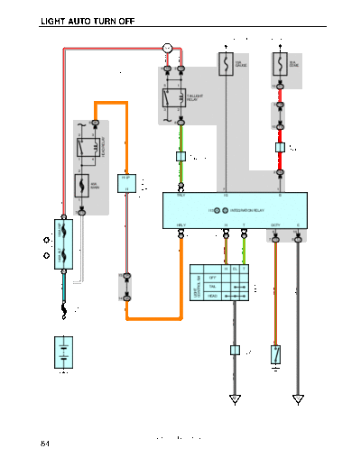
LIGHT AUTO TURN OFF
FROM POWER SOURCE SYSTEM (SEE PAGE 52)
W- R
I4
W- R
W- R
10A 10A
GAUGE DOME
* 1 : W/ DOOR LOCK CONTROL 4 1B 2 1B
* 2 : W/O DOOR LOCK CONTROL
5 1 12 2J
R- W
TAILLIGHT
RELAY
3 1W
3 2
8 2K 6 1C
10 1V
R
G- R
2 3
HEAD RELAY
A
O
J18
JUNCTION
B CONNECTOR
J5
JUNCTION A
1 4 CONNECTOR
R
B
LIGHT RELAY (MAIN)
2 6
G- R
2 1M
DAYTIME RUNNING
H- LP
40A 9 A (* 1)
MAIN
H 5 B (* 2) 7 1
7 TRLY IG B
D4
W- R
1
I13 A , B INTEGRATION RELAY
3 2B
1 B
100A INP
HRLY H T DCTY E
R- L
11 A 12 A 10 A (* 1) 6 10
FUSIBLE LINK BLOCK
6 B 7 B 4 B (* 2)
F8 A , F9 B
7 1S 8 1J
R- G
G- O
140A ALT
W
O
13 14
H EL T
1 A
COMBINATION SW
15 3A
CONTROL SW
OFF
B- L
TAIL
W- B
R- G
LIGHT
C12
HEAD
14 3A
16
FL MAIN
O
3. 0W
W- B
DOOR COURTESY SW
CONNECTOR
B 1
JUNCTION
BATTERY
J3
B
FRONT LH
D16
W- B
ED IJ
2001 SIENNA (EWD420U)
84
SYSTEM OUTLINE
With the ignition SW turned on, the current flows to TERMINAL 7 of the integration relay through GAUGE fuse.
Voltage is applied at all times to the integration relay through the taillight relay (Coil side), and to the integration relay through
the daytime running light relay (Main).
1. NORMAL LIGHTING OPERATION
With the light control SW turned to TAIL position, a signal is input into the integration relay. Accordingly, the current flows to
the integration relay to TERMINAL 14 of the light control SW to TERMINAL 16 to GROUND, and taillight relay causes
taillights to turn on.
With the light control SW turned to HEAD position, a signal is input into the integration relay. Accordingly, the current flows to
the integration relay to TERMINAL 13 of the light control SW to TERMINAL 16 to GROUND in the headlight circuit, and the
taillight relay and HEAD relay turn the lights on. The taillight circuit operation is same as above.
2. LIGHT AUTO TURN OFF OPERATION
With the lights on and the ignition SW turned off (Input signal goes to TERMINAL 7 of the integration relay), when the driver's
door is opened (Input signal goes to TERMINAL 6 of the integration relay), the relay operates and the current which flows to
the integration relay in the taillight circuit and the integration relay in the headlight circuit is cut off.
As a result, all lights are turned off automatically.
SERVICE HINTS
HEAD RELAY
2-1 : Closed with the light control SW at HEAD position or the dimmer SW at FLASH position
: Closed with the engine running and the parking brake is released
TAILLIGHT RELAY
3-5 : Closed with the light control SW at TAIL or HEAD position
D16 DOOR COURTESY SW FRONT LH
1-GROUND : Continuity with the driver's door open
I13 (A), (B) INTEGRATION RELAY
7-GROUND : Approx. 12 volts with the ignition SW at ON position
6-GROUND : Continuity with the driver's door open
1-GROUND : Always approx. 12 volts
10-GROUND : Always continuity
(A) 9, (B) 5-GROUND : Always approx. 12 volts
(A) 12, (B) 7-GROUND : Continuity with the light control SW at HEAD position
(A) 10, (B) 4-GROUND : Continuity with the light control SW at TAIL or HEAD position
: PARTS LOCATION
Code See Page Code See Page Code See Page
C12 34 F9 B 32 J5 35
D4 34 A 35 J18 35
I13
D16 36 B 35
F8 A 32 J3 35
2001 SIENNA (EWD420U)
85
LIGHT AUTO TURN OFF
,,,
,,, : JUNCTION BLOCK AND WIRE HARNESS CONNECTOR
,,,
Code See Page Junction Block and Wire Harness (Connector Location)
1B
1C
22 Cowl Wire and Driver Side J/B No.1 (Lower Finish Panel)
No 1
1J
1M
1S 22 Floor Wire and Driver Side J/B No.1 (Lower Finish Panel)
1V
22 Cowl Wire and Driver Side J/B No.1 (Lower Finish Panel)
No 1
1W
2B 24 Engine Room Main Wire and Engine Room J/B No.2 (Engine Compartment Left)
2J
24 Cowl Wire and Engine Room J/B No 2 (Engine Compartment Left)
No.2
2K
3A 26 Cowl Wire and J/B No.3 (Behind the Combination Meter)
: GROUND POINTS
Code See Page Ground Points Location
ED 40 Near the Left Front Suspension Support
IJ 42 Right Cowl Side Panel
: SPLICE POINTS
Code See Page Wire Harness with Splice Points Code See Page Wire Harness with Splice Points
I4 44 Cowl Wire
2001 SIENNA (EWD420U)
86
MEMO
2001 SIENNA (EWD420U)
87
◦ Jabse Service Manual Search 2026 ◦ Jabse Pravopis ◦ onTap.bg ◦ Other service manual resources online : Fixya ◦ eServiceinfo