Service Manuals, User Guides, Schematic Diagrams or docs for : . Car Manuals Toyota Sienna 1998-2003 Approved FSM 22 systemci 034pw
<< Back | HomeMost service manuals and schematics are PDF files, so You will need Adobre Acrobat Reader to view : Acrobat Download Some of the files are DjVu format. Readers and resources available here : DjVu Resources
For the compressed files, most common are zip and rar. Please, extract files with Your favorite compression software ( WinZip, WinRAR ... ) before viewing. If a document has multiple parts, You should download all, before extracting.
Good luck. Repair on Your own risk. Make sure You know what You are doing.
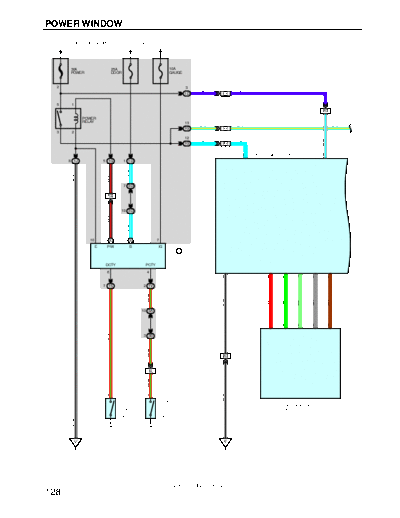
Image preview - the first page of the document
>> Download 034pw documenatation <<
Text preview - extract from the document
POWER WINDOW
FROM POWER SOURCE SYSTEM (SEE PAGE 52)
1
30A 25A 10A
POWER DOOR GAUGE
2 3 3
V V
1D IG1
5 1
1 IA3
POWER
RELAY 13 3
L- Y L- Y L- Y
1G IJ1
3 2
12 5
L L
W- L
1G IA3
P11
6 POWER WINDOW MASTER SW 7
8 1J 5 1G 1 1D
L- W
W- B
B- R
7 3D
1 IG2
19 3D
B- R
L- W
10 24 A 15 A 7
E P/W B IG
I13 A
INTEGRATION
RELAY
DCTY PCTY
6 4
1 8 4 17 14 2
7 1S 2 1V
R- G
W- B
GR
BR
LG
G
R
10 3A
1 2 4 5 6
R- G
3 3B
R- G
6 IA3
3 II2
R- G
DOOR COURTESY
DOOR COURTESY
1 1
W- B
SW FRONT RH
SW FRONT LH
P12
POWER WINDOW MOTOR
FRONT LH
D16
D17
W- B
IJ IF
2001 SIENNA (EWD420U)
128
FROM POWER SOURCE SYSTEM (SEE PAGE 52)
15A
ECU- IG
8 1D
J9
B- R
JUNCTION
CONNECTOR
4 6 5
B- R B- R A A B- R
IA3 1G 1W
L- Y
P11
11 POWER WINDOW MASTER SW
L- Y
13 15
R- L
W
8 IA1 3 IA1
G- W
R- L
8 IJ2 3 IJ2
G- W
R- L
5 2
CONTROL SW FRONT RH
SU SD
B 4 L- Y
POWER WINDOW
DOWN
UP
U D
3 1
P10
G
R
2 1
M
P13
POWER WINDOW MOTOR
FRONT RH
2001 SIENNA (EWD420U)
129
POWER WINDOW
SYSTEM OUTLINE
1. MANUAL DOWN OR UP OPERATION (DRIVER'S SIDE)
When the power window master SW is pressed one step, the current flows from the power window master SW TERMINAL 4
to power window motor front LH to power window master SW TERMINAL 8 to GROUND, and rotates the motor to open the
window.
When the power window master SW is pulled one step, the current flows from the power window master SW TERMINAL 8 to
power window motor front LH to power window master SW TERMINAL 4 to GROUND, and rotates the motor to close the
window.
2. AUTO DOWN OR UP OPERATION (DRIVER'S SIDE)
When the power window master SW is pushed two steps, the power window master SW determines it is in auto mode and
the current flows from the power window master SW TERMINAL 4 to power window motor front LH to power window master
SW TERMINAL 8 to GROUND, and rotates the motor to open the window automatically.
When the power window master SW is pulled two steps, the power window master SW determines it is in auto mode and the
current flows from the power window master SW TERMINAL 8 to power window motor front LH to power window master SW
TERMINAL 4 to GROUND, and rotates the motor to close the window automatically.
3. MANUAL OPERATION (FRONT PASSENGER'S WINDOW)
With the power window control SW front RH pulled to the up side, the current flowing from TERMINAL 4 of the power window
control SW flows to TERMINAL 3 of the power window control SW to TERMINAL 2 of the power window motor to TERMINAL
1 to TERMINAL 1 of the power window control SW to TERMINAL 2 to TERMINAL 15 of the master SW to TERMINAL 1 to
GROUND and causes the power window motor front RH to rotate in the up direction. The up operation continues only while
the power window SW is pulled to the up side. When the window descends, the current flowing to the motor flows in the
opposite direction, from TERMINAL 1 to TERMINAL 2, and the motor rotates in reverse. When the window lock SW is
pushed to the lock side, the ground circuit to the front RH window becomes open.
As a result, even if Open/Close operation of the front RH window is attempted, the current from TERMINAL 1 of the power
window master SW is not grounded, so the motor does not rotate, therefore the front RH window can not be operated. This
is how the window lock function operates.
4. CATCHING PREVENTION FUNCTION (DRIVER'S SIDE)
When any foreign matter is caught in the window during power window up operation, the pulse sensor in the power window
motor detects the changes in the number of motor rotations and forcibly opens the door window 50 mm, or when the window
opening is less than 200 mm, it opens the window until the opening is 200 mm.
5. KEY OFF POWER WINDOW OPERATION
It is possible to operate the power window for approx. 43 seconds after the ignition SW is turned from on to off. However,
when the door is opened while the window is being operated, the power window operation is stopped even though 43
seconds have not elapsed.
SERVICE HINTS
P11 POWER WINDOW MASTER SW
7-GROUND : Always approx. 12 volts
11-GROUND : Approx. 12 volts with the ignition SW at ON or ST position
: Approx. 12 volts with key off power window operation
1-GROUND : Always continuity
4-GROUND : Continuity with power window master SW at MANUAL UP position
: Continuity with power window master SW at AUTO UP position
8-GROUND : Continuity with power window master SW at MANUAL DOWN position
: Continuity with power window master SW at AUTO DOWN position
WINDOW LOCK SW
Open with the window lock SW at lock position
: PARTS LOCATION
Code See Page Code See Page Code See Page
D16 36 J9 35 P12 37
D17 36 P10 37 P13 37
I13 A 35 P11 37
2001 SIENNA (EWD420U)
130
,,, : JUNCTION BLOCK AND WIRE HARNESS CONNECTOR
,,,
,,,
Code See Page Junction Block and Wire Harness (Connector Location)
1D 22 Cowl Wire and Driver Side J/B No.1 (Lower Finish Panel)
1G 22 Instrument Panel Wire and Driver Side J/B No.1 (Lower Finish Panel)
1J 22 Cowl Wire and Driver Side J/B No.1 (Lower Finish Panel)
1S 22 Floor Wire and Driver Side J/B No.1 (Lower Finish Panel)
1V
22 Cowl Wire and Driver Side J/B No.1 (Lower Finish Panel)
No 1
1W
3A
3B 26 Cowl Wire and J/B No.3 (
(Behind the Combination Meter)
)
3D
: CONNECTOR JOINING WIRE HARNESS AND WIRE HARNESS
Code See Page Joining Wire Harness and Wire Harness (Connector Location)
IA1
42 Front Door LH Wire and Instrument Panel Wire (Left Kick Panel)
IA3
IG1
42 Instrument Panel Wire and Cowl Wire (Behind the Combination Meter)
IG2
II2 44 Floor No.2 Wire and Cowl Wire (Right Kick Panel)
IJ1
44 Front Door RH Wire and Instrument Panel Wire (Right Kick Panel)
IJ2
: GROUND POINTS
Code See Page Ground Points Location
IF 42 Left Kick Panel
IJ 42 Right Cowl Side Panel
2001 SIENNA (EWD420U)
131
◦ Jabse Service Manual Search 2026 ◦ Jabse Pravopis ◦ onTap.bg ◦ Other service manual resources online : Fixya ◦ eServiceinfo