Service Manuals, User Guides, Schematic Diagrams or docs for : . Car Manuals Toyota Sienna 2004-2007 Approved SRM 04 11 20um5 w140001

<< Back | Home

Most service manuals and schematics are PDF files, so You will need Adobre Acrobat Reader to view : Acrobat Download Some of the files are DjVu format. Readers and resources available here : DjVu Resources
For the compressed files, most common are zip and rar. Please, extract files with Your favorite compression software ( WinZip, WinRAR ... ) before viewing. If a document has multiple parts, You should download all, before extracting.
Good luck. Repair on Your own risk. Make sure You know what You are doing.


Image preview - the first page of the document
w140001


>> Download w140001 documenatation <<

Text preview - extract from the document
                                                                                                             11-21
                                                        FUEL   -   FUEL SUCTION TUBE ASSY W/ PUMP & GAGE
                                                                                                              110T2-02


Removal & Installation and Disassembly & Reassembly
1.   DISCHARGE FUEL SYSTEM PRESSURE (See page 11-1 )
2.   REMOVE CHARCOAL CANISTER PROTECTOR (See page 12-1 1)
3.   REMOVE FUEL TANK FILLER HOSE COVER (See page 11-30 )
4.   REMOVE FUEL TANK ASSY (See page 11-30 )
5.   REMOVE FUEL TANK TO FILLER PIPE HOSE (See page 11-30 )


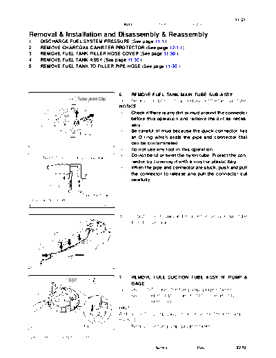
                                                   6.  REMOVE FUEL TANK MAIN TUBE SUB-ASSY
                            Tube Joint Clip        (a) Remove the tube joint clip, and pull out the fuel main tube.
                                                   NOTICE:
                                                    S  Check if there is any dirt or mud around the connector
                                                       before this operation and remove the dirt as neces-
                                                       sary.
                                                    S  Be careful of mud because the quick connector has
                                                       an O-ring which seals the pipe and connector that
                                          A79524       can be contaminated.
                                                    S  Do not use any tool in this operation.
       Nylon Tube                                   S  Do not bend or twist the nylon tube. Protect the con-
                            Fuel Tube Joint
                                                       nector by covering it with a vinyl or plastic bag.
                                                    S  When the pipe and connector are stuck, push and pull
                                                       the connector to release and pull the connector out
                                                       carefully.
         O-ring

                              Tube Joint Clip
 Fuel Suction Plate
                                          A81635


                                                   (b)     Unfasten the 4 claws and remove the fuel tank main tube
                                                           from the fuel tank.


                                          A79526


                                                   7.      REMOVE FUEL SUCTION TUBE ASSY W/ PUMP &
                      SST
                                                           GAGE
                                                   (a)     Using SST, loosen the fuel pump gauge retainer.
                                                           SST 09808-14020 (09808-01410, 09808-01420,
                                                                  09808-01430)
                                                   HINT:
                                                   A rib on the fuel pump gauge retainer can be fitted into a tip of
                                                   the SST.
                               Rib        A79525   (b) Remove the fuel pump gauge retainer.

 2005 SIENNA REPAIR MANUAL (RM1163U)

                                                                         Author :             Date :          2270
11-22
                                                     FUEL   -   FUEL SUCTION TUBE ASSY W/ PUMP & GAGE

                                                   (c)  Remove the fuel suction tube w/ pump & gage and the
                                                        gasket from the fuel tank.
                                                   NOTICE:
                                                   Be careful not bend the arm of the fuel sender gage.

                                                   8.    REMOVE VAPOR PRESSURE SENSOR ASSY
       Cover                Tube Joint Clip
                                                   (a)   Remove the cover.
                                                   (b)   Remove the tube joint clip and pull out the vapor pressure
                                                         sensor.


                                          A79767


                          Unlock                   9.    REMOVE FUEL SENDER GAGE ASSY
                                                   (a)   Disconnect the fuel sender gage connector.
                                                   (b)   Unlock the fuel sender gage and slide it to remove.
           (a)

                 Slide


                                          A79768


                                                   10. REMOVE FUEL SUCTION PLATE SUB-ASSY
                                Tape               (a) Using a screwdriver with the tip wrapped in tape, discon-
                                                       nect the 4 snap-claws from the claw holes and remove
                                                       the fuel suction plate.
                                                   NOTICE:
                                                   Do not damage the fuel suction plate and the fuel suction
                                                   support No. 1.

                                          A79769


                         Tape                      11.  REMOVE FUEL PUMP
 (a)
                                                   (a)  Disconnect the fuel pump connector.
                                                   (b)  Using a small screwdriver with the tip wrapped in tape,
                                                        disconnect the 2 claws from the claw holes and pull out
                                                        the fuel pump.
                                                   NOTICE:
                                                   Do not damage the fuel pump and the fuel suction plate.
                                                   (c) Remove the O-ring and the fuel pump spacer from the
                                          A79770        fuel pump.


2005 SIENNA REPAIR MANUAL (RM1163U)

                                                                       Author :             Date :             2271
                                                                                                            11-23
                                                 FUEL   -   FUEL SUCTION TUBE ASSY W/ PUMP & GAGE

                                               12.   REMOVE FUEL FILTER ASSY
                                               (a)   Using a small screwdriver, pry out the clip.
                                               (b)   Remove the fuel filter from the fuel pump.


                                      A79771


                                               13.   REMOVE FUEL TUBE JOINT NO.1
                           Tape
                                               (a)   Remove the connector.
                                               (b)   Using a screwdriver with the tip wrapped in tape, discon-
                                                     nect the snap-claw from the claw hole and pull out the
                                                     fuel tube joint No. 1.
                                               NOTICE:
          (a)
                                               Do not damage the fuel tube joint No. 1 and the fuel suction
                                               plate.
                                      A79772


                                               14.   REMOVE FUEL PUMP HARNESS
                                               (a)   Remove the fuel pump harness from the fuel tube joint
                                                     No. 1.


                                      A79773


                                               15.   REMOVE FUEL PRESSURE REGULATOR ASSY
                          Clip                 (a)   Remove the clip.
                                               (b)   Pull out the fuel pressure regulator from the fuel suction
                                                     plate.
                                               (c)   Remove the 2 O-rings from the fuel pressure regulator.


                                      A79774


                                               16.   INSTALL FUEL PRESSURE REGULATOR ASSY
      New O-ring                               (a)   Apply a light coat of gasoline or spindle oil to the 2 new
                                                     O-rings, and install it to the fuel pressure regulator.
                                               (b)   Apply a light coat of gasoline or spindle oil to the 2 O-rings
                                                     again, and install the fuel pressure regulator to the fuel
                                                     tube joint No. 1.
                                               (c)   Install the clip.
                                               17.   INSTALL FUEL PUMP HARNESS
                                      A79775


2005 SIENNA REPAIR MANUAL (RM1163U)

                                                                  Author :             Date :                2272
11-24
                                                   FUEL   -   FUEL SUCTION TUBE ASSY W/ PUMP & GAGE


           New O-ring                            18.   INSTALL FUEL TUBE JOINT NO.1
                                                 (a)   Apply a light coat of gasoline or spindle oil to a new O-
                                                       ring, and install it to the fuel tube joint No. 1.
                                                 (b)   Apply a light coat of gasoline or spindle oil to the O-ring
                                                       again, and install the fuel tube joint No. 1 to the fuel suc-
                                                       tion plate.
                                                 (c)   Connect the connector.
                                                 19.   INSTALL FUEL FILTER ASSY
                                        A79776   (a)   Install the fuel filter with a new clip.

                                                 20.   INSTALL FUEL PUMP
        New O-ring
                                                 (a)   Install the fuel pump spacer to the fuel pump.
                                                 (b)   Apply a light coat of gasoline or spindle oil to a new O-
                                                       ring, and install it to the fuel pump.
                                                 (c)   Apply a light coat of gasoline or spindle oil to the O-ring
 Fuel Pump                                             again, and install the fuel pump to the fuel suction plate.
 Spacer                                          (d)   Connect the fuel pump connector.

                                        A81604


                                                 21.   INSTALL FUEL SUCTION PLATE SUB-ASSY
                                                 (a)   Apply a light coat of gasoline or spindle oil to a new O-
                                                       ring, and install it to the fuel tube joint No. 1.
    New-O-ring
                                                 (b)   Apply a light coat of gasoline or spindle oil to the O-ring
                                                       again, and install the fuel suction plate to the fuel suction
                                                       support No. 1.
                                                 22.   INSTALL FUEL SENDER GAGE ASSY

                                        A79777


                                                 23. INSTALL VAPOR PRESSURE SENSOR ASSY
                           Tube Joint Clip       (a) Install the vapor pressure sensor with the tube joint clip.
                                                 NOTICE:
                                                  S  Check that there is no scratch or foreign objects on
                                                     the connecting parts.
                                                  S  Check that the fuel tube joint connector is fully in-
                                                     serted.
                               Collar             S  Check that the fuel tube joint clip is on the collar of the
                                        A81675       fuel tube joint.
                                                  S  After installing the tube joint clip, check if the fuel
                                                     tube joint connector is securely connected by pulling
                                                     it.


2005 SIENNA REPAIR MANUAL (RM1163U)

                                                                     Author :             Date :               2273
                                                                                                          11-25
                                                  FUEL   -   FUEL SUCTION TUBE ASSY W/ PUMP & GAGE


                  Arrow Mark                    24.   INSTALL FUEL SUCTION TUBE ASSY W/ PUMP &
                                                      GAGE
                                                NOTICE:
                                                Prior to assembly, all the new components must be stabi-
                                                lized at room temperature for minimum 12 hours.
                                                (a) Ensure gasket groove is clean and free of foreign par-
                                                      ticles.
                                                (b) Install a new gasket to the fuel tank.
                                       A79537   (c) Make sure that the gasket sits in the groove.
                                                (d) Align the arrow mark of the fuel suction tube w/ pump &
                                                      gage tube and the tank suction support.
                                                NOTICE:
                                                Be careful not bend the arm of the fuel sender gage.


                                                (e) Align marks on a new fuel pump gauge retainer and the
         Mark                                       fuel tank.
                                                (f) Position the fuel pump gauge retainer on top of the fuel
                                                    suction w/ pump & gage flange while pushing down the
                                                    flange on center.
                                                (g) While holding the fuel suction tube w/ pump & gage, tight-
                                                    en the pump gauge retainer one complete turn by hand.
                                                NOTICE:
                                       A79538    S  Make sure the fuel suction tube w/ pump & gage anti-
                                                    rotation tab is in the groove during above operation.
                                                 S  "S" arrow on the fuel tank indicates 0 degrees posi-
                                                    tion.


                                                (h)   Ensure that no cross threading occurred during installa-
                   SST
                                                      tion by checking the gap between the fuel pump gauge re-
                                                      tainer and the fuel tank. Confirm that the gap is even. If
                                                      cross threading occurred, remove the fuel pump gauge
                                                      retainer and repeat step (g).
                                                (i)   Using SST, tighten the fuel pump gauge retainer to the
                                                      specified torque.
                                                      SST 09808-14020 (09808-01410, 09808-01420,
                          Rib          A79525                 09808-01430)
                                                      Torque: 80 to 90 Nm (816 to 918 kgfcm, 59 to 67 ftlbf)
                                                NOTICE:
                            Triangle             S    No ratcheting effect allowed when tightening the fuel
                            Mark                      pump gauge retainer.
                                                 S    No grease or lubrication allowed on parts during
                                                      installation.
                                                HINT:
                                                A rib on the fuel pump gauge retainer can be fitted into a tip of
                                                the SST.
                                       A79539


2005 SIENNA REPAIR MANUAL (RM1163U)

                                                                   Author :             Date :             2274
11-26
                                                     FUEL     -   FUEL SUCTION TUBE ASSY W/ PUMP & GAGE

                                               (j)    Install the fuel pump gauge retainer by one and half turn
                                                      so that the triangle mark on the fuel pump gauge retainer
                                                      is between 510_ and 570_ from the start position.
                                               (k) If the triangle mark is not reached 510_, confirm that no
                                                      cross threading occurred by measuring the gap between
                                                      the fuel pump gauge retainer and the fuel tank.
                                               If cross threading occurred, replace the fuel pump gauge retain-
                                               er, the gasket and the tank suction tube support.


                                               (l)      Replace the tank suction tube support.
                                                        (1) Remove the tank suction tube support from the fuel
                                                             tank.


                                      A79527


                                                        (2)       Install the tank suction tube support to the fuel tank
                                                                  as shown in the illustration.


                                      A79536


                                               (m)      Put a mark on the fuel pump gauge retainer and the fuel
                                                        tank with paint. This will be the evidence that the fuel
                                                        pump gauge retainer had been removed.


           Paint Mark                 A81626


                   Tube Joint Clip             25. INSTALL FUEL TANK MAIN TUBE SUB-ASSY
                                               (a) Install in the fuel return tube with the tube joint clip.
                                               NOTICE:
                                                S  Check that there is no scratch or foreign objects on
                                                   the connecting part.
                                                S  Check that the fuel tube joint is inserted securely.
  Collar                                        S  Check that the tube joint clip is on the collar of the fuel
                                                   tube joint.
                                      A81605    S  After installing the tube joint clip, check that the fuel
                                                   tube joint has not been pulled off.
2005 SIENNA REPAIR MANUAL (RM1163U)

                                                                         Author :             Date :               2275
                                                                                         11-27
                                      FUEL   -   FUEL SUCTION TUBE ASSY W/ PUMP & GAGE

26.   INSTALL FUEL TANK TO FILLER PIPE HOSE (See page 11-30 )
27.   INSTALL FUEL TANK ASSY (See page 11-30 )
28.   CHECK FOR FUEL LEAKS (See page 11-4 )
29.   INSTALL FUEL TANK FILLER HOSE COVER (See page 11-30 )
30.   INSTALL CHARCOAL CANISTER PROTECTOR (See page 12-1 1)


2005 SIENNA REPAIR MANUAL (RM1163U)

                                                       Author :             Date :       2276


◦ Jabse Service Manual Search 2026 ◦ Jabse PravopisonTap.bg ◦ Other service manual resources online : FixyaeServiceinfo