Service Manuals, User Guides, Schematic Diagrams or docs for : . Car Manuals Toyota Sienna 2004-2007 Approved SRM 04 32 2041w x040001
<< Back | HomeMost service manuals and schematics are PDF files, so You will need Adobre Acrobat Reader to view : Acrobat Download Some of the files are DjVu format. Readers and resources available here : DjVu Resources
For the compressed files, most common are zip and rar. Please, extract files with Your favorite compression software ( WinZip, WinRAR ... ) before viewing. If a document has multiple parts, You should download all, before extracting.
Good luck. Repair on Your own risk. Make sure You know what You are doing.
Image preview - the first page of the document
>> Download x040001 documenatation <<
Text preview - extract from the document
32-18
                                                BRAKE   -   W/MASTER CYLINDER BRAKE BOOSTER ASSY
                                                                                                          320VB-02


REPLACEMENT
NOTICE:
 S  Do not adjust the brake booster push rod.
 S  Do not change the combination of the diameter converting unit and brake.
1.  REMOVE FRONT WHEEL
2.  DRAIN BRAKE FLUID
NOTICE:
Wash the brake fluid off immediately if it attaches to any painted surfaces.
3.  BATTERY NEGATIVE TERMINAL
4.  REMOVE FRONT DOOR SCUFF PLATE LH
5.  REMOVE COWL SIDE TRIM BOARD LH
(a) Remove the nut and cowl trim board plate LH.
6.  REMOVE INSTRUMENT PANEL FINISH PANEL SUB-ASSY LOWER LH
(a) Remove the 2 bolts and instrument panel finish panel sub-assy lower LH.
7.  REMOVE INSTRUMENT PANEL SAFETY PAD INSERT SUB-ASSY NO.1
(a) Remove the 4 bolts and instrument panel safety pad insert sub-assy No.1.
8.  REMOVE COWL TOP PANEL SUB-ASSY OUTER FRONT (See page 55-33 )
9.  REMOVE AIR CLEANER ASSEMBLY WITH HOSE
10. REMOVE BRAKE ACTUATOR ASSY (W/O VSC) (See page 32-43 )
    SST 09023-00101
11. REMOVE BRAKE ACTUATOR ASSY (W/ VSC) (See page 32-46 )
    SST 09023-00101
12. REMOVE BRAKE LINE
(a) Remove the front brake tube No.1, front brake tube No.2, front brake tube No.3 and front brake tube
    No.4.
(b) Remove the rear brake tube No.1 and rear brake tube No.2.
13. REMOVE PUSH ROD PIN
(a) Remove the push rod pin from the brake booster push rod .


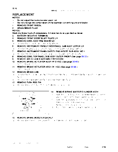
                                               14.   REMOVE BRAKE MASTER CYLINDER ASSY
                                               (a)   Slide the clip and disconnect the brake master cylinder re-
                                                     sevoir hose from the brake master cylinder union.
                                               (b)   Slide the clip and disconnect the vacuum hose from the
                                                     brake vucuum check valve assy.
                                               (c)   Remove the 4 nuts and clevis.
                                               (d)   Pull out the brake booster with master cylinder.

                                      G24262


15.     REMOVE BRAKE BOOSTER GASKET
(a)     Remove the brake booster gasket from the brake booster with master cylinder.


2005 SIENNA REPAIR MANUAL (RM1163U)

                                                                  Author :             Date :               2766
                                                                                                         32-19
                                                BRAKE   -   W/MASTER CYLINDER BRAKE BOOSTER ASSY

16.   REMOVE BRAKE VACUUM CHECK VALVE ASSY
(a)   Remove the brake vacuum check valve assy and check valve grommet from the brake booster assy.
17.   INSTALL BRAKE VACUUM CHECK VALVE ASSY
(a)   Install the brake vacuum check valve assy and check valve grommet to the brake booster assy.
18.   INSTALL BRAKE BOOSTER GASKET
(a)   Install a new brake booster gasket to the brake booster with master cylinder.


                                                19.   INSTALL BRAKE MASTER CYLINDER ASSY
                                                (a)   Install the brake booster assy with the 4 nuts.
                                                      Torque: 13 Nm (130 kgfcm, 9 ftlbf)
                                                (b)   Slide the clip and connect the brake master cylinder res-
                                                      ervoir hose to the brake master cylinder union.
                                                (c)   Slide the clip and connect the vacuum hose from the
                                                      brake vucuum check valve assy.

                                       G24262


20.   INSTALL PUSH ROD PIN
(a)   Install the push rod pin to the brake booster push rod.
21.   INSTALL BRAKE LINE
(a)   Install the front brake tube No.1, front brake tube No.2, front brake tube No.3 and front brake tube No.4.
      Torque: 15 Nm (155 kgfcm, 11 ftlbf)
(b)   Install the rear brake tube No.1and rear brake tube No.2.
      Torque: 15 Nm (155 kgfcm, 11 ftlbf)
22.   INSTALL BRAKE ACTUATOR ASSY (W/ VSC) (See page 32-46 )
      SST 09023-00101
23.   INSTALL BRAKE ACTUATOR ASSY (W/O VSC) (See page 32-43 )
      SST 09023-00101
24.   INSTALL AIR CLEANER ASSEMBLY WITH HOSE
25.   FILL RESERVOIR WITH BRAKE FLUID (See page 32-4 )
26.   BLEED MASTER CYLINDER (See page 32-4 )
      SST 09023-00101
27.   BLEED BRAKE LINE (See page 32-4 )
28.   CHECK FLUID LEVEL IN RESERVOIR (See page 32-4 )
29.   CHECK BRAKE FLUID LEAKAGE
30.   INSTALL INSTRUMENT PANEL SAFETY PAD INSERT SUB-ASSY NO.1
(a)   Install the instrument panel safety pad insert sub-assy No.1 with the 4 bolts.
31.   INSTALL INSTRUMENT PANEL FINISH PANEL SUB-ASSY LOWER LH
(a)   Install the instrument panel finish panel sub-assy lower LH with the 2 bolts.
32.   INSTALL COWL SIDE TRIM BOARD LH
(a)   Install the cowl trim board plate LH with the nut.
33.   INSTALL FRONT DOOR SCUFF PLATE LH
34.   INSTALL COWL TOP PANEL SUB-ASSY OUTER FRONT (See page 55-33 )
35.   INSTALL FRONT WHEEL
      Torque: 103 Nm (1,050 kgfcm, 76 ftlbf)


 2005 SIENNA REPAIR MANUAL (RM1163U)

                                                                  Author :            Date :              2767
32-20
                                      BRAKE   -   W/MASTER CYLINDER BRAKE BOOSTER ASSY

36.     INSPECT BRAKE PEDAL HEIGHT (See page 32-6 )
37.     CHECK BRAKE ACTUATOR WITH TOYOTA HAND-HELD TESTER
        (See page 05-386 or 05-435 )


2005 SIENNA REPAIR MANUAL (RM1163U)

                                                        Author :            Date :       2768
◦ Jabse Service Manual Search 2026 ◦ Jabse Pravopis ◦ onTap.bg ◦ Other service manual resources online : Fixya ◦ eServiceinfo