Service Manuals, User Guides, Schematic Diagrams or docs for : . Car Manuals Toyota Sienna 2004-2007 Approved SRM 06 20um4 x040001
<< Back | HomeMost service manuals and schematics are PDF files, so You will need Adobre Acrobat Reader to view : Acrobat Download Some of the files are DjVu format. Readers and resources available here : DjVu Resources
For the compressed files, most common are zip and rar. Please, extract files with Your favorite compression software ( WinZip, WinRAR ... ) before viewing. If a document has multiple parts, You should download all, before extracting.
Good luck. Repair on Your own risk. Make sure You know what You are doing.
Image preview - the first page of the document
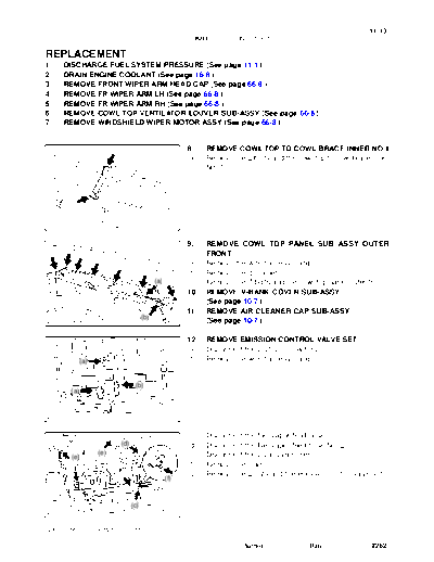
>> Download x040001 documenatation <<
Text preview - extract from the document
11-13
FUEL - FUEL INJECTOR ASSY
110T0-03
REPLACEMENT
1. DISCHARGE FUEL SYSTEM PRESSURE (See page 11-1 )
2. DRAIN ENGINE COOLANT (See page 16-8 )
3. REMOVE FRONT WIPER ARM HEAD CAP (See page 66-8 )
4. REMOVE FR WIPER ARM LH (See page 66-8 )
5. REMOVE FR WIPER ARM RH (See page 66-8 )
6. REMOVE COWL TOP VENTILATOR LOUVER SUB-ASSY (See page 66-8 )
7. REMOVE WINDSHIELD WIPER MOTOR ASSY (See page 66-8 )
8. REMOVE COWL TOP TO COWL BRACE INNER NO.1
(a) Remove the 2 bolts and the cowl top to cowl brace inner
No. 1.
A79761
9. REMOVE COWL TOP PANEL SUB- ASSY OUTER
FRONT
(a) Remove the wire harness clamp.
(b) Remove the grommet.
(a) (c) Remove the 7 bolts and the cowl top panel outer front.
10. REMOVE V-BANK COVER SUB-ASSY
(See page 10-7 )
11. REMOVE AIR CLEANER CAP SUB-ASSY
(b)
A79760 (See page 10-7 )
12. REMOVE EMISSION CONTROL VALVE SET
(a) Disconnect the 2 VSV connectors.
(a) (b) Remove the wire harness clamp.
(b)
(a)
A79751
(c) Disconnect the fuel vapor feed hose.
(d) (d) Disconnect the fuel vapor feed hose No. 2.
(e) (e) Disconnect the 2 vacuum hoses.
(e)
(f) Remove the clamp.
(g) Remove the 2 nuts and the emission control valve set.
(f)
(c)
A79752
2005 SIENNA REPAIR MANUAL (RM1163U)
Author : Date : 2262
11-14
FUEL - FUEL INJECTOR ASSY
13. REMOVE INTAKE AIR SURGE TANK
(d) (a) Disconnect throttle motor connector.
(b) Disconnect the water by-pass hose No. 3.
(c) Disconnect the water by-pass hose No. 2.
(c) (a) (d) Disconnect the union to check valve hose.
(b)
A81623
(e) Disconnect the ventilation hose.
(e)
A79706
(f) Remove the 2 set nuts of the pressure feed tube.
A79707
(h) (g) Remove the 2 bolts and the engine hunger No. 1.
(g) (h) Remove the 2 bolts and the surge tank stay No. 1.
(i) Remove the 2 bolts and the surge tank stay No. 2.
(i)
A81674
(j) Using a socket hexagon wrench 8, remove the 4 bolts.
(k) Remove the 2 nuts, the emission control valve bracket
and the intake air surge tank.
(l) Remove the gasket from the intake air surge tank.
A81622
2005 SIENNA REPAIR MANUAL (RM1163U)
Author : Date : 2263
11-15
FUEL - FUEL INJECTOR ASSY
14. SEPARATE FUEL PIPE SUB-ASSY NO.1
(a) Remove the bolt and the fuel pipe No. 1.
(b) (b) Remove the fuel pressure pulsation damper and the 2
gaskets.
(c) Remove the fuel pipe No. 2 union bolt and the 2 gaskets.
(c) (a)
A79710
15. REMOVE FUEL INJECTOR ASSY
(a) Disconnect the 6 fuel injector connectors.
A79711
(b) Remove the 4 bolts and the 2 fuel delivery pipes together
with the 6 fuel injectors.
NOTICE:
Be careful not to drop the fuel injectors when removing the
delivery pipe.
A79712
L2 (c) Remove the 4 delivery pipe No. 1 spacers (L1) and the
6 insulators (L2) from the intake manifold.
L1
L1
L2
G39631
(d) Pull out the fuel injector from the fuel delivery pipe.
A81137
2005 SIENNA REPAIR MANUAL (RM1163U)
Author : Date : 2264
11-16
FUEL - FUEL INJECTOR ASSY
16. INSTALL FUEL INJECTOR ASSY
New O-ring
(a) Install new grommets to the each fuel injector.
(b) Apply a light coat of spindle oil or gasoline to new O-rings,
and install it to the each fuel injector.
New Grommet
A79762
(c) Apply a light coat of spindle oil or gasoline on the place
where the fuel delivery pipe contacts the O-ring.
Turn (d) Push the fuel injector while twisting it back and forth to
install it in the fuel delivery pipe.
NOTICE:
Push
S Be careful not to twist the O-ring.
S After installing the fuel injectors, check that they
turns smoothly. If not, reinstall it with a new O-ring.
A81139 (e) Install 6 new insulators and the 4 delivery pipe No. 1
spacers to the intake manifold.
(f) Place the 2 fuel delivery pipes and 6 fuel injectors togeth-
er to the intake manifold.
NOTICE:
Be careful not to drop the fuel injectors when installing the
fuel delivery pipe.
(g) Temporarily install 4 bolts which are used to attach the
fuel delivery pipe to the intake manifold.
(h) Check that the fuel injectors rotate smoothly.
Turn If fuel injectors do not rotate smoothly, the probable cause is in-
A81601
correct installation of O-ring. Replace with the O-ring.
(i) Tighten the 4 bolts.
Torque: 10 Nm (102 kgfcm, 7 ftlbf)
(j) Connect the 6 fuel injector connectors.
17. INSTALL FUEL PIPE SUB-ASSY NO.1
(a) Install 2 new gaskets and the fuel pipe No. 2 union bolt.
Torque: 33 Nm (331 kgfcm, 24 ftlbf)
(b) Install 2 new gaskets and the fuel pressure pulsation damper.
Torque: 33 Nm (331 kgfcm, 24 ftlbf)
(c) Install the fuel pipe No. 1 with the bolt.
Torque: 20 Nm (199 kgfcm, 14 ftlbf)
18. INSTALL INTAKE AIR SURGE TANK
(a) Install a new gasket to the intake air surge tank.
(b) Install the intake air surge tank and the emission control valve bracket with the 2 nuts.
Torque: 28 Nm (286 kgfcm, 21 ftlbf)
(c) Using a socket hexagon wrench 8, tighten the 4 bolts.
Torque: 28 Nm (286 kgfcm, 21 ftlbf)
(d) Install the surge tank stay No. 2 with the 2 bolts.
Torque: 20 Nm (199 kgfcm, 14 ftlbf)
(e) Install the surge tank stay No. 1 with the 2 bolts.
Torque: 20 Nm (199 kgfcm, 14 ftlbf)
2005 SIENNA REPAIR MANUAL (RM1163U)
Author : Date : 2265
11-17
FUEL - FUEL INJECTOR ASSY
(f) Install the engine hunger No. 1 with the 2 bolts.
Torque: 20 Nm (199 kgfcm, 14 ftlbf)
(g) Install the pressure feed tube with the 2 nuts.
Torque: 7.8 Nm (80 kgfcm, 69 in.lbf)
(h) Connect the ventilation hose.
(i) Connect the union to check valve hose.
(j) Connect the water by-pass hose No. 2.
(k) Connect the water by-pass hose No. 3.
(l) Connect the throttle motor connector.
19. INSTALL EMISSION CONTROL VALVE SET
Torque: 8.0 Nm (82 kgfcm, 71 in.lbf)
20. INSTALL AIR CLEANER CAP SUB-ASSY (See page 10-7 )
21. ADD ENGINE COOLANT (See page 16-8 )
22. CHECK FOR FUEL LEAKS (See page 11-4 )
23. CHECK FOR ENGINE COOLANT LEAKS (See page 16-1 )
24. INSTALL V-BANK COVER SUB-ASSY (See page 10-7 )
25. INSTALL COWL TOP PANEL SUB-ASSY OUTER FRONT
Torque: 7.5 Nm (76 kgfcm, 66 in.lbf)
26. INSTALL COWL TOP TO COWL BRACE INNER NO.1
Torque: 7.5 Nm (76 kgfcm, 66 in.lbf)
27. INSTALL WINDSHIELD WIPER MOTOR ASSY (See page 66-8 )
28. INSTALL COWL TOP VENTILATOR LOUVER SUB-ASSY
29. INSTALL FR WIPER ARM RH (See page 66-8 )
30. INSTALL FR WIPER ARM LH (See page 66-8 )
31. INSTALL FRONT WIPER ARM HEAD CAP
2005 SIENNA REPAIR MANUAL (RM1163U)
Author : Date : 2266
◦ Jabse Service Manual Search 2026 ◦ Jabse Pravopis ◦ onTap.bg ◦ Other service manual resources online : Fixya ◦ eServiceinfo