Service Manuals, User Guides, Schematic Diagrams or docs for : . Car Manuals Toyota Sienna 2004-2007 Approved SRM 09 200f0 i740001

<< Back | Home

Most service manuals and schematics are PDF files, so You will need Adobre Acrobat Reader to view : Acrobat Download Some of the files are DjVu format. Readers and resources available here : DjVu Resources
For the compressed files, most common are zip and rar. Please, extract files with Your favorite compression software ( WinZip, WinRAR ... ) before viewing. If a document has multiple parts, You should download all, before extracting.
Good luck. Repair on Your own risk. Make sure You know what You are doing.


Image preview - the first page of the document
i740001


>> Download i740001 documenatation <<

Text preview - extract from the document
                                                                                                                                    14-1
                                  ENGINE MECHANICAL        -   ENGINE


ENGINE
                                                                                                                                  1404Q-12


INSPECTION
1.   INSPECT COOLANT (See page 16-1 )
2.   INSPECT ENGINE OIL
3.   INSPECT BATTERY
     Standard specific gravity: 1.25 to 1.29 at 20_C (68_F)
4.   INSPECT AIR CLEANER FILTER ELEMENT SUB-ASSY
5.   INSPECT SPARK PLUG (See page 18-3 )

                                                6.     INSPECT V-RIBBED BELT
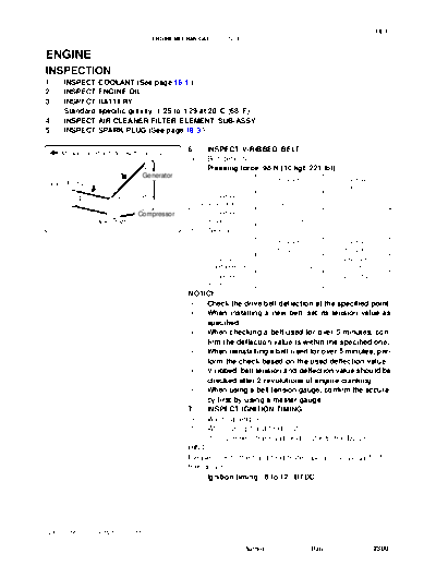
     Measuring Points for Belt Looseness
                                                (a)    Belt deflection:
                                                       Pressing force: 98 N (10 kgf, 221 lbf)
                               Generator
                                                                                      New belt                      Used belt
 Vane Pump
                                                                                      mm (in.)                      mm (in.)
                                                        V ribbed belt                 9.1 to 10.5                  11.0 to 13.5
                                                  (For fan and generator)          (0.358 to 0.413)              (0.433 to 0.531)

                             Compressor                 V ribbed belt                   8 to 10                      11 to 14
              Crank Shaft                             (for vane pump)              (0.315 to 0.394)              (0.433 to 0.551)
                                       A52000
                                                (b)    Tension:
                                                                                     New belt                       Used belt
                                                                                     N (kg , lb)                    N (kg , lb)
                                                        V ribbed belt               617 to 853                      294 to 490
                                                  (for fan and generator)     (63 to 87 , 139 to 192)          (30 to 50 , 66 to 110)
                                                        V ribbed belt               588 to 686                      245 to 392
                                                      (for vane pump)         (60 to 70 , 132 to 154)          (25 to 40 , 55 to 88)

                                                NOTICE:
                                                 S    Check the drive belt deflection at the specified point.
                                                 S    When installing a new belt, set its tension value as
                                                      specified.
                                                 S    When checking a belt used for over 5 minutes, con-
                                                      firm the deflection value is within the specified one.
                                                 S    When reinstalling a belt used for over 5 minutes, per-
                                                      form the check based on the used deflection value.
                                                 S    V-ribbed belt tension and deflection value should be
                                                      checked after 2 revolutions of engine cranking.
                                                 S    When using a belt tension gauge, confirm the accura-
                                                      cy first by using a master gauge.
                                                7.    INSPECT IGNITION TIMING
                                                (a) Warm up engine.
                                                (b) When using hand-held tester.
                                                      (1) Connect the hand-held tester to the DLC3.
                                                HINT:
                                                Please refer to the hand-held tester operator's manual for fur-
                                                ther details.
                                                      Ignition timing : 8 to 12_ BTDC


 2005 SIENNA REPAIR MANUAL (RM1163U)

                                                                        Author :                      Date :                      2300
14-2
                                 ENGINE MECHANICAL         -   ENGINE

                                               (c) When not using hand-held tester.
                  TC                               (1) Using SST, connect terminals 13 (TC) and 4 (CG)
                                                        of DLC3.
                                                   SST 09843-18040
                                               NOTICE:
                                                S  Be careful not to connect incorrectly. It causes break-
                                                   age of the engine.
                                                S  Turn OFF all electrical systems.
                       CG             A51075    S  Operate the inspection when the cooling fan motor is
                                                   turned OFF.
                                                   (2) Remove the V-bank cover.


                                                     (3)       Pull out the wire harness as shown in the illustration.
                                                               Connect the clip of the timing light to the engine.
                                               NOTICE:
                                               Use a timing light which can detect the first signal.
                                                     (4) Inspect ignition timing at idle.
                                                     Ignition timing : 8 to 12_ BTDC
                                               NOTICE:
                                               When checking the ignition timing, the transmission is in
         Black                        A52005   neutral position.
                                               HINT:
                                               After engine rpm is kept at 1,000 to 1,300 rpm. for 5 seconds,
                                               check that it returns idle speed.
                                                     (5) Disconnect terminals 13 (TC) and 4 (CG) of the
                                                           DLC3.
                                                     (6) Inspect ignition timing at idle.
                                                     Ignition timing : 7 to 24_ BTDC
                                                     (7) Confirm that ignition timing moves to advanced
                                                           angle when the engine rpm is increased.
                                                     (8) Remove the timing light.
                                               8.    INSPECT ENGINE IDLE SPEED
                                               (a) Warm up the engine.
                                               (b) When using hand-held tester.
                                                     (1) Connect the hand-held tester to the DLC3.
                                                     Idle speed: 550 to 650 rpm.
                                               HINT:
                                               Please refer to the hand-held tester operator's manual for fur-
                                               ther details.


2005 SIENNA REPAIR MANUAL (RM1163U)

                                                                        Author :            Date :               2301
                                                                                                             14-3
                                 ENGINE MECHANICAL      -   ENGINE

                                               (c) When not using hand-held tester.
                               TAC                 (1) Using SST, connect the tachometer test probe to
                                                         terminal 9 (TAC) of DLC3.
                                                   SST 09843-18040
                                                   (2) Check the idle speed.
                                                   Idle speed: 550 to 650 rpm.
                                               NOTICE:
                                                S  Check idle speed with cooling fan OFF.
                                      A52006    S  Switch off all accessories and air conditioning.

                                               9.    INSPECT COMPRESSION
                                               (a)   Stop a warm engine.
                                               (b)   Disconnect the injector connectors.
                                               (c)   Remove the intake air surge tank. (See page 14-7 )
                                               (d)   Remove the ignition coil.
                                               (e)   Remove the spark plugs.


                                               (f)   Inspect cylinder compression pressure.
                                                     SST 09992-00500
                                                     (1) Insert a compression gauge into the spark plug
                                                           hole.
                                                     (2) While cranking the engine, measure the compres-
                                                           sion pressure.
                                                     Compression pressure:
                                                     1.5 MPa (15.3 kgf/cm2, 218 psi)
                                      P19471         Minimum pressure:
                                                     1.0 MPa (10.2 kgf/cm2, 145 psi)
                                                     Difference between each cylinder:
                                                     100 kPa (1.0 kgf/cm2, 15 psi)
                                               NOTICE:
                                                S    Always use a fully charged battery to obtain engine
                                                     speed of 250 rpm or more.
                                                S    Check other cylinder's compression pressure in the
                                                     same way.
                                                S    This measurement must be done in as short a time as
                                                     possible.
                                                     (3) If the cylinder compression is low, pour a small
                                                           amount of engine oil into the cylinder through the
                                                           spark plug hole and inspect again.
                                               HINT:
                                                S    If adding oil increases the compression, it is likely that the
                                                     piston rings and/or cylinder bore are worn or damaged.
                                                S    If pressure stays low, a valve may be sticking or seating
                                                     improperly, or there may be leakage past the gasket.


2005 SIENNA REPAIR MANUAL (RM1163U)

                                                                 Author :               Date :               2302
14-4
                                  ENGINE MECHANICAL       -   ENGINE

10. INSPECT CO/HC
(a) Start the engine.
(b) Race the engine at 2,500 rpm. for approx. 180 seconds.
(c) Insert CO/HC meter testing probe at least 40 cm (1.3 ft) into tailpipe during idling.
(d) Immediately check CO/HC concentration at idle and/or 2,500 rpm.
HINT:
 S    Complete the measuring within 3 minutes.
 S    When doing the 2 mode (idle and 2,500 rpm) test, the procedure may vary according to local regula-
      tions.
(e) If the CO/HC concentration does not comply with regulations, troubleshoot in the order given below.
      (1) Check heated oxygen sensor operation. (See page 12-6 )
      (2) See the table below for possible causes, and then inspect and correct the applicable causes if
             necessary.
       CO            HC               Problems                                             Causes
                                                         4. Faulty ignitions:
                                                         S Incorrect timing
                                                         S Fouled, shorted or improperly gapped plugs
Normal        High          Rough idle
                                                         5. Incorrect valve clearance
                                                         6. Leaky intake and exhaust valves
                                                         7. Leaky cylinders
                                                         1. Vacuum leaks:
                                                         S PCV hoses
                            Rough idle                   S Intake manifold
Low           High
                            (Fluctuating HC reading)     S Throttle body
                                                         S Brake booster line
                                                         2. Lean mixture causing misfire
                                                         1. Restricted air filter
                                                         2. Plugged PCV valve
                                                         3. Faulty EFI systems:
                            Rough idle                   S Faulty pressure regulator
High          High                                       S Defective water temperature sensor
                            (Black smoke from exhaust)
                                                         S Defective mass air-flow meter
                                                         S Faulty ECM
                                                         S Faulty injectors
                                                         S Faulty throttle position sensor


2005 SIENNA REPAIR MANUAL (RM1163U)

                                                                       Author :                     Date :   2303


◦ Jabse Service Manual Search 2026 ◦ Jabse PravopisonTap.bg ◦ Other service manual resources online : FixyaeServiceinfo