Service Manuals, User Guides, Schematic Diagrams or docs for : . Car Manuals Toyota Sienna 2004-2007 Approved SRM 09 20qeo x040001

<< Back | Home

Most service manuals and schematics are PDF files, so You will need Adobre Acrobat Reader to view : Acrobat Download Some of the files are DjVu format. Readers and resources available here : DjVu Resources
For the compressed files, most common are zip and rar. Please, extract files with Your favorite compression software ( WinZip, WinRAR ... ) before viewing. If a document has multiple parts, You should download all, before extracting.
Good luck. Repair on Your own risk. Make sure You know what You are doing.


Image preview - the first page of the document
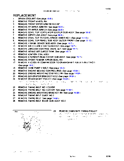
x040001


>> Download x040001 documenatation <<

Text preview - extract from the document
                                                                                                   14-99
                                 ENGINE MECHANICAL     -   CAMSHAFT (RH BANK)
                                                                                                   141AR-02


REPLACEMENT
1.    DRAIN COOLANT (See page 16-8 )
2.    REMOVE FRONT WHEEL RH
3.    REMOVE FRONT WIPER ARM HEAD CAP
4.    REMOVE FR WIPER ARM RH (See page 66-8 )
5.    REMOVE FR WIPER ARM LH (See page 66-8 )
6.    REMOVE COWL TOP VENTILATOR LOUVER SUB-ASSY (See page 66-8 )
7.    REMOVE WIPER LINK ASSY (See page 66-8 )
8.    REMOVE COWL TOP TO COWL BRACE INNER NO.1 (See page 11-13 )
9.    REMOVE COWL TOP PANEL SUB-ASSY OUTER FRONT (See page 11-13 )
10.   REMOVE V-BANK COVER SUB-ASSY (See page 14-7 )
11.   REMOVE AIR CLEANER CAP SUB-ASSY (See page 10-7 )
12.   REMOVE EMISSION CONTROL VALVE SET (See page 14-7 )
13.   REMOVE INTAKE AIR SURGE TANK (See page 14-7 )
14.   REMOVE IGNITION COIL ASSY
15.   REMOVE CYLINDER HEAD COVER SUB-ASSY (See page 14-7 )
16.   REMOVE FRONT FENDER APRON SEAL RH
17.   REMOVE V (COOLER COMPRESSOR TO CRANKSHAFT PULLEY) BELT NO.1
      (See page 14-5 )
18.   REMOVE VANE PUMP V BELT (See page 14-5 )
19.   REMOVE ENGINE MOVING CONTROL ROD (See page 14-84 )
20.   REMOVE ENGINE MOUNTING STAY NO.2 RH (See page 14-84 )
21.   REMOVE GENERATOR BRACKET NO.2 (See page 14-84 )
22.   REMOVE CRANKSHAFT PULLEY (See page 14-84 )
      SST 09213-54015 (91651-60855), 09330-00021, 09950-50013 (09951-05010, 09952-05010,
             09953-05020, 09954-05031)
23.   REMOVE TIMING BELT NO.1 COVER
24.   REMOVE TIMING BELT NO.2 COVER (See page 14-84 )
25.   REMOVE ENGINE MOUNTING BRACKET RH (See page 14-84 )
26.   REMOVE TIMING BELT GUIDE NO.2
27.   REMOVE TIMING BELT (See page 14-84 )
28.   REMOVE TIMING BELT IDLER SUB-ASSY NO.2


 RH                                            29.   REMOVE CAMSHAFT TIMING PULLEY
                                               (a)   Using SST, remove the bolt and the RH timing pulley.
                                                     SST 09960- 10010 (09962- 01000, 09963- 01000),
                                                            09249-63010


 SST


                                      A78761


2005 SIENNA REPAIR MANUAL (RM1163U)

                                                                 Author :         Date :            2398
14-100
                                    ENGINE MECHANICAL          -   CAMSHAFT (RH BANK)


 LH                                              (b)    Using SST, remove the LH timing pulley.
                                                        SST 09960-10010 (09962-01000, 09963-01000)
                                                 HINT:
 SST                                             Arrange the camshaft timing pulleys (RH and LH sides) so that
                                                 they can be returned to the original locations when re-assem-
                                                 bling.


                                        A78762


                                                 30.  REMOVE TIMING BELT NO.3 COVER
                  Clamp                          (a)  Disconnect the 3 engine wire harness clamps from the
                                     Clamp            timing belt No.3 cover.
                                                 (b) Remove the 6 bolts and the timing belt cover.
                                                 31. REMOVE CAMSHAFT
                                                 NOTICE:
                                                 Since the thrust clearance of the camshaft is small, the
                                                 camshaft must be kept level while it is being removed. If the
                                   Clamp
                                        A05077   camshaft is not kept level, damage to the cylinder head or
                                                 to the camshaft may result. To avoid this, the following
                                                 steps should be carried out.


                                                 (a)    Align the timing marks (2 dot marks) of the camshaft drive
                                                        and the driven gears by turning the camshaft with a
                                                        wrench.


                       Align
                                        A78706


           Main Gear                             (b) Secure the exhaust camshaft sub-gear to the main gear
                                 Sub-Gear            with a service bolt.
                                                     Torque: 5.4 Nm (55 kgfcm, 48 in.lbf)
                                                 Recommended service bolt
                                                 Thread diameter                        6 mm
                                                 Thread pitch                           1.0 mm
                               Service Bolt      Bolt length                            16 to 20 mm
                                                 HINT:
                                        A78707   When removing the camshaft, make certain that the torsional
                                                 spring force of the sub-gear has been eliminated by installation
                                                 of the service bolt.


2005 SIENNA REPAIR MANUAL (RM1163U)

                                                                          Author :               Date :      2399
                                                                                                                                14-101
                                                ENGINE MECHANICAL         -   CAMSHAFT (RH BANK)


                                                    2            (c) Using several steps, loosen and remove the 10 bearing
                                            6
                                                             1
                                                                     cap bolts uniformly in the sequence shown in the illustra-
                                   10                                tion. Remove the 5 bearing caps and the camshaft.
                                                5                NOTICE:
                      8
                                        9                         S  Do not pry out the camshaft.
                                                                  S  Be careful not to damage the portion of the cylinder
          4               7
                                                                     head receiving the shaft thrust.
              3
                                                        A78708


                                                                 32. REMOVE NO.2 CAMSHAFT
                                                    1
                                                                 (a) Using several steps, loosen and remove the 10 bearing
                                        5
                          9                                          cap bolts uniformly in the sequence shown in the illustra-
                                                         2
                                            6                        tion. Remove the 5 bearing caps and the No. 2 camshaft.
              7
                                                                 NOTICE:
      3                       10
                                                                  S  Do not pry out the camshaft.
                  8
          4                                                       S  Be careful not to damage the portion of the cylinder
                                                                     head receiving the shaft thrust.
                                                        A78709   (b) Remove the oil seal from the No. 2 camshaft.

                                                                 33. REMOVE CAMSHAFT TIMING GEAR ASSY
                                                                 NOTICE:
                                                                 Do not remove or install the camshaft timing gear (VVT-i)
                                                                 unless you are changing the VVT-i or the camshaft.
                                                                 (a) Clamp the camshaft in a vise on the hexagonal lobe.
                                                                 NOTICE:
                                                                 Be careful not to damage the camshaft.

                                                        A05739


                                                                 (b)      Using a 46 mm socket wrench, remove the lock nut by
                                                                          turning it clockwise.
                                                                 NOTICE:
                                                                  S       Remove it with the lock-pin engaged and locked at
                                                                          the maximum delay angle position.
                                                                  S       The lock nut has LH threads.
                                                                  S       Never use any tool other than the socket wrench. Oth-
                                                                          er tools will deform the cam angle rotor.
                                                        A05740   (c) Remove the camshaft VVT-i.
                                                                 NOTICE:
                                                                 Never remove the 3 bolts on the gear.
                                                                 If it is difficult to remove VVT-i, tap it lightly using a plastic-faced
                                                                 hammer and then remove it.


2005 SIENNA REPAIR MANUAL (RM1163U)

                                                                                     Author :               Date :                2400
14-102
                                  ENGINE MECHANICAL    -   CAMSHAFT (RH BANK)

                                               34. REMOVE CAMSHAFT SUB GEAR
                                               (a) Clamp the camshaft in a vise on the hexagonal lobe.
                                               NOTICE:
                                               Be careful not to damage the camshaft.


                                      P12596


                                               (b)   Using SST, turn the sub-gear counterclockwise, and re-
                            SST                      move the service bolt.
                                                     SST 09960-10010 (09962-01000, 09963-00500)


                                      A78715


                                               (c)   Using snap ring pliers, remove the snap ring.
                                               (d)   Remove the wave washer, the camshaft sub-gear and
                                                     the camshaft gear bolt washer.


                                      A52353


                                               35. INSTALL CAMSHAFT SUB GEAR
                                               (a) Clamp the camshaft in a vise on the hexagonal lobe.
                                               NOTICE:
                                               Be careful not to damage the camshaft.


                                      P12595


                                               (b)   Install the camshaft gear bolt washer and the camshaft
         Wave Washer
                                                     sub-gear .
  Camshaft
                                               HINT:
  Sub-Gear
                                               Attach the pins on the gears to the gear bolt washer ends.
                                               (c) Install the wave washer.

                        Camshaft Gear
                        Bolt Washer

                                      A78732


2005 SIENNA REPAIR MANUAL (RM1163U)

                                                                  Author :          Date :             2401
                                                                                                       14-103
                                 ENGINE MECHANICAL     -   CAMSHAFT (RH BANK)

                                               (d)   Using snap ring pliers, install the snap ring.


                                      A52353


                                               (e)   Using SST, align the holes of the camshaft main gear and
                                                     the sub-gear by turning camshaft sub-gear counter-
                                SST                  clockwise, and temporarily install a service bolt.
                                                     SST 09960-10010 (09962-01000, 09963-00500)
                                               (f)   Align the gear teeth of the main gear and sub-gear, and
                                                     tighten the service bolt.
                                                     Torque: 5.4 Nm (55 kgfcm, 48 in.lbf)
                                               NOTICE:
                                      A78733   Be careful not to damage the camshaft journals.
                                               HINT:
                                               When installing the camshaft, make certain that the torsional
                                               spring force of the sub-gear has been eliminated by installation
                                               of the service bolt.


                                               36.   INSTALL CAMSHAFT TIMING GEAR ASSY
                                               (a)   Align the alignment pin with the alignment pin groove and
                                                     install VVT-i on the camshaft.
                                               NOTICE:
                                               Install it with the lock-pin engaged and locked at the maxi-
                                               mum delay angle position.
                                               (b) Apply engine oil on the nut, the mounting surface of VVT-i
                       Align                         and the screw threads.
                                      A78734   NOTICE:
                                                S    Be sure to apply the oil, otherwise the specified
                                                     torque cannot be obtained.
                                                S    New nut must be used when replacing VVT-i unit.


                                               (c) Using a 46 mm socket wrench, install and tighten a lock
                                                   nut by turning it counterclockwise.
                                                   Torque: 150 Nm (1,530 kgfcm, 111 ftlbf)
                                               NOTICE:
                                                S  The lock nut has LH threads.
                                                S  Never use any tool other than the socket wrench. Oth-
                                                   er tools will deform the cam angle rotor.

                                      A05738


2005 SIENNA REPAIR MANUAL (RM1163U)

                                                                 Author :             Date :             2402
14-104
                                 ENGINE MECHANICAL      -   CAMSHAFT (RH BANK)

                                               37. INSTALL NO.2 CAMSHAFT
                                               NOTICE:
                                               Since the thrust clearance of the camshaft is small, the
                                               camshaft must be kept level while it is being removed. If the
                                               camshaft is not kept level, damage to the cylinder head or
                                               to the camshaft may result. To avoid this, the following
                                               steps should be carried out.
                                               (a) Apply new engine oil to the thrust portion and journal of
                                                    the camshaft.

                                               (b)   Place the No. 2 camshaft at a 90_ angle of the timing mark
              90_                                    (2 dot marks) on the cylinder head.
                                               (c)   Apply MP grease to a new oil seal lip.


                                      A78735


                                               (d) Install the oil seal to the camshaft.
                                               NOTICE:
                                                S  Do not turn over the oil seal lip.
                                                S  Insert the oil seal until it stops.
                         Front                 (e) Remove any old packing material from the contact sur-
                                                   face.


                                      A78736


                                               (f) Apply seal packing to the No. 1 bearing cap as shown in
                                                   the illustration.
                                                   Seal packing: Part No. 08826-00080 or equivalent
                                               NOTICE:
                                                S  Install the No. 1 bearing cap within 5 minutes after ap-
                                                   plying seal packing.
                                                S  Do not expose the seal to engine oil within 2 hours af-
                                                   ter installing.
         Seal Packing
                                      A78737


                                               (g)   Install the 5 bearing caps in their proper locations.
                                               (h)   Apply a light coat of engine oil on the threads of the bear-
                                                     ing cap bolts.


                                      A05283


2005 SIENNA REPAIR MANUAL (RM1163U)

                                                                   Author :            Date :               2403
                                                                                                                           14-105
                                             ENGINE MECHANICAL         -   CAMSHAFT (RH BANK)


                                             10
                                                              (i)  Using several steps, tighten the 10 bearing cap bolts uni-
                                 6
                                                                   formly in the sequence shown in the illustration.
                     2                            9
                                                                   Torque: 16 Nm (163 kgfcm, 12 ftlbf)
                                                              38. INSTALL CAMSHAFT
         4                           5
                                                              NOTICE:
                         1
8                                                             Since the thrust clearance of the camshaft is small, the
             3                                                camshaft must be kept level while it is being removed. If the
    7                                                         camshaft is not kept level, damage to the cylinder head or
                                                     A78738   to the camshaft may result. To avoid this, the following
                                                              steps should be carried out.
                                                              (a) Apply new engine oil to the thrust portion and journal of
                                                                   the camshaft.


                                                              (b)   Align the timing marks (2 dot marks) of the camshaft drive
                                                                    with the driven gears.
                                                              (c)   Place the camshaft on the cylinder head.


Align

                                                     A78739


                                                              (d)   Install the 5 bearing caps in their proper locations.
                                                              (e)   Apply a light coat of engine oil on the threads of the bear-
                                                                    ing cap bolts.


                                                     A05204


                                                 9            (f)   Using several steps, tighten the 10 bearing cap bolts uni-
                                         5                          formly in the sequence shown in the illustration.
                                 1                   10             Torque: 16 Nm (163 kgfcm, 12 ftlbf)
                                             6                (g)   Remove the service bolt.
                     3
                                     2                        39.   INSTALL TIMING BELT NO.3 COVER
                                                              (a)   Visually check for cracks and breaks in the gasket of the
         7                   4
                                                                    timing belt cover.
                 8                                            HINT:
                                                     A78740   If there is a trace that water is entering at the visual check, repair
                                                              it with seal packing when the crack length is within 2 to 3 cm
                                                              (0.79 to 1.18 in.). Replace the gasket when the crack length is
                                                              3 to 4 cm (1.18 to 1.57 in.) and more.


2005 SIENNA REPAIR MANUAL (RM1163U)

                                                                                 Author :               Date :               2404
14-106
                                    ENGINE MECHANICAL          -   CAMSHAFT (RH BANK)

                                                 (b)  When the timing belt cover gasket is needed to replace,
         Seal Packing
                           Gasket                     follow the procedure below.
                                                      (1) Repair the cracks and breaks by applying the seal
                                                            packing to the damaged area.
                                                      Seal packing: Part No. 08826-00080 or equivalent
                                                 NOTICE:
                                                 When applying the seal packing, apply it as wide and high
                                                 as the gasket.
                                        A78748   (c) When the timing belt cover gasket is needed to replace,
                                                      follow the procedure below.
                                                      (1) Using a screwdriver and a gasket scraper, remove
                                                            the remaining gasket.
                                                 NOTICE:
                                                 Be careful not to damage the timing belt cover.

                                                         (2)       Remove the backing paper from a new gasket, and
         E                          E                              affix the gasket along the groove of the timing belt
                    F
                                                                   cover as shown in the illustration.
                                                 NOTICE:
                                                  S    Affix the gasket in the center of the groove.
                                                  S    At the corners, try to keep the gasket thickness uni-
                                  Joining
                    D                                  form.
       Joining                  G Line
       Line                                      HINT:
 Joining Portion                                       Gasket             D               E             F           G
               Gasket                                                  335 mm          180 mm        133 mm       72 mm
                                                       Length
                                                                      (13.19 in.)     (7.09 in.)    (5.24 in.)   (2.83 in.)

                                                         (3)If there is a gap on the joint of the gasket, apply seal
              Seal Packing                                  packing to close the gap.
                                        A78749        Seal packing: Part No. 08826-00080 or equivalent
                                                 NOTICE:
                                                 When applying the seal packing, apply it as wide and high
                                                 as the gasket.
                                                 (d) Install the timing belt cover with the 6 bolts.
                                                      Torque: 8.5 Nm (87 kgfcm, 76 in.lbf)

                                                 40.     INSTALL CAMSHAFT TIMING PULLEY
     Front         Front                         (a)     Pay attention to the orientation of the belt guide, install the
                                                         camshaft timing pulley with the belt guide properly ori-
                                                         ented and tighten the bolt temporally.
                                                 HINT:
                                                 S       Face the belt guide of the RH timing pulley toward front
                                                         of the engine.
                                                 S       Face the belt guide of the LH timing pulley toward rear of
                                        A78750           the engine.


2005 SIENNA REPAIR MANUAL (RM1163U)

                                                                           Author :                Date :                2405
                                                                                                    14-107
                                 ENGINE MECHANICAL     -   CAMSHAFT (RH BANK)


 RH
                                               (b)   Using SST, tighten the RH pulley bolt.
                                                     SST 09960- 10010 (09962- 01000, 09963- 01000),
                SST                                           09249-63010
                                                     Torque: 125 Nm (1,275 kgfcm, 92 ftlbf)
                                               NOTICE:
                                               The torque indicated above is used without SST on exten-
           150 mm                              sion tool. If you are using extension tools, find the reading
                                               of the torque wrench by the formula.
                                      A78763   (See page 01-5 )
                                                     Extended length:
                                                     SST (09249-63010) 150mm (5.91 in.)


 LH                                            (c)   Using SST, tighten the LH pulley bolt.
                                                     SST 09960-10010 (09962-01000, 09963-01000)
                                                     Torque: 125 Nm (1275 kgfcm, 92 ftlbf)
 SST


                                      A78762


41.    INSTALL TIMING BELT IDLER SUB-ASSY NO.2
       Torque: 43 Nm (438 kgfcm, 32 ftlbf)
42.    INSPECT TIMING BELT (See page 14-84 )
43.    INSTALL TIMING BELT (See page 14-84 )
       SST 09960-10010 (09962-01000, 09963-01000)
44.    INSTALL CHAIN TENSIONER ASSY NO.1 (See page 14-84 )
45.    INSTALL TIMING BELT GUIDE NO.2 (See page 14-84 )
46.    INSTALL ENGINE MOUNTING BRACKET RH (See page 14-84 )
47.    INSTALL TIMING BELT NO.2 COVER (See page 14-84 )
48.    INSTALL TIMING BELT NO.1 COVER (See page 14-84 )
49.    INSTALL CRANKSHAFT PULLEY (See page 14-84 )
       SST 09213-54015 (91651-60855), 09330-00021
50.    INSTALL GENERATOR BRACKET NO.2 (See page 14-84 )
51.    INSTALL ENGINE MOUNTING STAY NO.2 RH (See page 14-84 )
52.    INSTALL ENGINE MOVING CONTROL ROD (See page 14-84 )
53.    INSPECT VALVE CLEARANCE (See page 14-7 )
54.    ADJUST VALVE CLEARANCE (See page 14-7 )
       SST 09248-55040 (09248-05410, 09248-05420)
55.    INSTALL VANE PUMP V BELT (See page 14-5 )
56.    INSTALL V (COOLER COMPRESSOR TO CRANKSHAFT PULLEY) BELT NO.1
       (See page 14-5 )
57.    INSPECT DRIVE BELT DEFLECTION AND TENSION (REFERENCE) (See page 14-1 )
58.    INSTALL CYLINDER HEAD COVER SUB-ASSY (See page 14-7 )
59.    INSTALL IGNITION COIL ASSY (See page 14-7 )
60.    INSTALL INTAKE AIR SURGE TANK (See page 14-7 )
2005 SIENNA REPAIR MANUAL (RM1163U)

                                                                 Author :          Date :             2406
14-108
                                 ENGINE MECHANICAL   -   CAMSHAFT (RH BANK)

61.   INSTALL EMISSION CONTROL VALVE SET (See page 14-7 )
62.   INSTALL AIR CLEANER CAP SUB-ASSY (See page 10-7 )
63.   CONNECT VACUUM HOSE (See page 14-33 )
64.   INSTALL V-BANK COVER SUB-ASSY (See page 14-7 )
65.   INSTALL COWL TOP PANEL SUB-ASSY OUTER FRONT (See page 11-13 )
66.   INSTALL COWL TOP TO COWL BRACE INNER NO.1 (See page 11-13 )
67.   INSTALL WIPER LINK ASSY (See page 66-8 )
68.   INSTALL FR WIPER ARM LH (See page 66-8 )
69.   INSTALL FR WIPER ARM RH (See page 66-8 )
70.   INSTALL FRONT WHEEL RH (See page 14-5 )
71.   ADD COOLANT (See page 16-8 )
72.   CHECK FOR ENGINE COOLANT LEAKS (See page 16-8 )


2005 SIENNA REPAIR MANUAL (RM1163U)

                                                                Author :      Date :   2407


◦ Jabse Service Manual Search 2026 ◦ Jabse PravopisonTap.bg ◦ Other service manual resources online : FixyaeServiceinfo