Service Manuals, User Guides, Schematic Diagrams or docs for : . Car Manuals Toyota Sienna 2004-2007 Approved SRM 09 20qf2 x040001
<< Back | HomeMost service manuals and schematics are PDF files, so You will need Adobre Acrobat Reader to view : Acrobat Download Some of the files are DjVu format. Readers and resources available here : DjVu Resources
For the compressed files, most common are zip and rar. Please, extract files with Your favorite compression software ( WinZip, WinRAR ... ) before viewing. If a document has multiple parts, You should download all, before extracting.
Good luck. Repair on Your own risk. Make sure You know what You are doing.
Image preview - the first page of the document
>> Download x040001 documenatation <<
Text preview - extract from the document
14-129
ENGINE MECHANICAL - CYLINDER HEAD GASKET
141AV-03
REPLACEMENT
1. DISCHARGE FUEL SYSTEM PRESSURE (See page 11-1 )
2. DRAIN COOLANT (See page 16-8 )
3. DRAIN ENGINE OIL (See page 17-23 )
4. REMOVE FRONT WHEEL RH
5. REMOVE FRONT WIPER ARM HEAD CAP
6. REMOVE FR WIPER ARM RH (See page 66-8 )
7. REMOVE FR WIPER ARM LH (See page 66-8 )
8. REMOVE COWL TOP VENTILATOR LOUVER SUB-ASSY (See page 66-8 )
9. REMOVE WIPER LINK ASSY (See page 66-8 )
10. REMOVE COWL TOP TO COWL BRACE INNER NO.1 (See page 11-13 )
11. REMOVE COWL TOP PANEL SUB-ASSY OUTER FRONT (See page 11-13 )
12. REMOVE V-BANK COVER SUB-ASSY (See page 14-7 )
13. REMOVE AIR CLEANER CAP SUB-ASSY (See page 10-7 )
14. REMOVE EMISSION CONTROL VALVE SET (See page 14-7 )
15. REMOVE INTAKE AIR SURGE TANK (See page 14-7 )
16. DISCONNECT FUEL PIPE SUB-ASSY NO.1 (See page 11-1 )
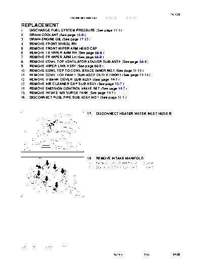
17. DISCONNECT HEATER WATER INLET HOSE B
A78399
18. REMOVE INTAKE MANIFOLD
(a) Remove the nut and the ground cable.
(b) Disconnect the 6 fuel injector connectors.
A79753
2005 SIENNA REPAIR MANUAL (RM1163U)
Author : Date : 2428
14-130
ENGINE MECHANICAL - CYLINDER HEAD GASKET
(c) In order to remove the intake manifold, using several
steps, remove the 9 bolts and the 2 nuts in the sequence
shown in the illustration.
4 10
2
8 6
3 11 5
1
7 9
A79754
19. DISCONNECT RADIATOR HOSE INLET
20. REMOVE WATER OUTLET
(a) Disconnect the radiator reserve tank hose.
(b) Disconnect the engine coolant temperature sensor con-
nector.
(c) Remove the clamp.
(d) Remove the 2 bolts, the 2 nuts and the 2 washers.
(e) Lock the hose clamp as shown in the illustration and re-
move the water outlet together with the water by-pass
hose No. 1.
(f) Remove the 2 gaskets from the 2 cylinder heads.
A79756
21. REMOVE FRONT FENDER APRON SEAL RH
22. REMOVE V (COOLER COMPRESSOR TO CRANKSHAFT PULLEY) BELT NO.1
(See page 14-5 )
23. REMOVE VANE PUMP V BELT (See page 14-5 )
24. REMOVE ENGINE MOVING CONTROL ROD (See page 14-84 )
25. REMOVE ENGINE MOUNTING STAY NO.2 RH (See page 14-84 )
26. REMOVE GENERATOR BRACKET NO.2 (See page 14-84 )
27. REMOVE CRANKSHAFT PULLEY (See page 14-84 )
SST 09213-54015 (91651-60855), 09330-00021, 09950-50013 (09951-05010, 09952-05010,
09953-05020, 09954-05031)
2005 SIENNA REPAIR MANUAL (RM1163U)
Author : Date : 2429
14-131
ENGINE MECHANICAL - CYLINDER HEAD GASKET
28. REMOVE TIMING BELT NO.1 COVER
29. REMOVE TIMING BELT NO.2 COVER (See page 14-84 )
30. REMOVE ENGINE MOUNTING BRACKET RH (See page 14-84 )
31. REMOVE TIMING BELT GUIDE NO.2
32. REMOVE TIMING BELT (See page 14-84 )
33. REMOVE TIMING BELT IDLER SUB-ASSY NO.2
34. REMOVE CAMSHAFT TIMING PULLEY (See page 14-99 )
SST 09960-10010 (09962-01000, 09963-01000), 09249-63010
35. REMOVE TIMING BELT NO.3 COVER (See page 14-99 )
36. SEPARATE VANE PUMP ASSY (See page 14-33 )
37. REMOVE PROPELLER SHAFT (4WD DRIVE TYPE) (See page 30-6 )
SST 09325-20010
38. REMOVE EXHAUST PIPE ASSY FRONT (2WD DRIVE TYPE) (See page 15-2 )
39. REMOVE EXHAUST PIPE ASSY CENTER (4WD DRIVE TYPE) (See page 15-6 )
40. REMOVE EXHAUST MANIFOLD HEAT INSULATOR NO.1
41. REMOVE MANIFOLD STAY
42. REMOVE EXHAUST MANIFOLD SUB-ASSY RH (2WD
DRIVE TYPE)
(a) Disconnect the heated oxygen sensor connector.
(b) Using several steps, loosen and remove the 6 nuts in the
sequence shown in the illustration.
3 6 1
(c) Remove the exhaust manifold RH and the gasket from
the cylinder head RH.
43. REMOVE EXHAUST MANIFOLD CONVERTER
SUB-ASSY (4WD DRIVE TYPE)
(a) Disconnect the heated oxygen sensor connector.
2 5 4
A78400
(b) Using several steps, loosen and remove the 6 nuts in the
sequence shown in the illustration.
3 6 1
(c) Remove the exhaust manifold RH and the gasket from
the cylinder head RH.
2 5 4
A78400
44. REMOVE IGNITION COIL ASSY
45. REMOVE CYLINDER HEAD COVER SUB-ASSY (See page 14-7 )
46. REMOVE CAMSHAFT (See page 14-99 )
47. REMOVE NO.2 CAMSHAFT (See page 14-99 )
2005 SIENNA REPAIR MANUAL (RM1163U)
Author : Date : 2430
14-132
ENGINE MECHANICAL - CYLINDER HEAD GASKET
48. REMOVE CYLINDER HEAD SUB-ASSY
(a) Disconnect the VVT sensor connector.
(b) Disconnect the camshaft timing oil control valve connec-
tor.
(c) Remove the nut and disconnect the engine wire harness
clamp.
A78401
(d) Using an 8 mm hexagon wrench, remove the hexagon
bolt.
Front
A78716
(e) Using several steps, loosen the 8 cylinder head bolts uni-
formly in the sequence shown in the illustration. Remove
Front
the 8 cylinder head bolts and the plate washers.
2 7 5 3 NOTICE:
S Be careful not to drop washers into the cylinder head.
S Head warpage or cracking could result from remov-
4 6 8 1 ing bolts in an incorrect order.
A78717
49. REMOVE CYLINDER HEAD GASKET
50. INSPECT CYLINDER HEAD SET BOLT
(a) Using vernier calipers, measure the tension portion diam-
Tension Portion eter of the bolt.
Standard outside diameter:
8.95 to 9.05 mm (0.3524 to 0.3563 in.)
Minimum outside diameter: 8.75 mm (0.3445 in.)
If the diameter is less than minimum, replace the bolt.
A78721
2005 SIENNA REPAIR MANUAL (RM1163U)
Author : Date : 2431
14-133
ENGINE MECHANICAL - CYLINDER HEAD GASKET
51. INSTALL CYLINDER HEAD GASKET
Front (a) Place a new cylinder head gasket on the cylinder block
with the R mark upward.
NOTICE:
S Remove any oil from the contact surface.
S Be careful of the installing orientation.
S Place the cylinder head on the gasket carefully in or-
der not to damage the gasket at the bottom part of the
A78324 head.
52. INSTALL CYLINDER HEAD SUB-ASSY
NOTICE:
The cylinder head bolts are tightened in 2 successive
steps.
(a) Apply a light coat of engine oil on the threads of the cylin-
der head bolts.
(b) Install the plate washers to the cylinder head bolts.
(c) Using several steps, install and tighten the 8 cylinder
head bolts uniformly in the sequence shown in the illustra-
Front
tion.
7 2 4 6 Torque: 54 Nm (550 kgfcm, 40 ftlbf)
5 3 1 8
A78717
(d) Mark the front side of each cylinder head bolt head with
paint as shown in the illustration.
90_ (e) Retighten the cylinder head bolts by 90_ in the same se-
quence as step (c).
Front (f) Check that the painted mark is now at a 90_ angle to the
front.
Painted mark
A78730
(g) Using an 8 mm socket hexagon wrench, install the hexa-
gon bolt.
Front
Torque: 19 Nm (189 kgfcm, 14 ftlbf)
(h) Connect the engine wire harness clamp with the nut.
Torque: 8.4 Nm (85 kgfcm, 74 in.lbf)
A78716
2005 SIENNA REPAIR MANUAL (RM1163U)
Author : Date : 2432
14-134
ENGINE MECHANICAL - CYLINDER HEAD GASKET
53. INSTALL NO.2 CAMSHAFT (See page 14-99 )
54. INSTALL CAMSHAFT (See page 14-99 )
55. INSTALL CYLINDER HEAD COVER SUB-ASSY (See page 14-7 )
56. INSTALL IGNITION COIL ASSY (See page 14-7 )
57. INSTALL EXHAUST MANIFOLD SUB-ASSY RH (2WD
DRIVE TYPE)
4 1 6
(a) Install a new gasket and the exhaust manifold RH with the
6 nuts. Using several steps, tighten the nuts uniformly in
the sequence shown in the illustration.
Torque: 49 Nm (500 kgfcm, 36 ftlbf)
(b) Retighten nut 1 and 2 shown in the illustration.
5 2 3
A78400
58. INSTALL EXHAUST MANIFOLD CONVERTER
SUB-ASSY (4WD DRIVE TYPE)
4 1 6
(a) Install a new gasket and the exhaust manifold RH with the
6 nuts. Using several steps, tighten the nuts uniformly in
the sequence shown in the illustration.
Torque: 49 Nm (500 kgfcm, 36 ftlbf)
(b) Retighten nut 1 and 2 shown in the illustration.
5 2 3
A78400
59. INSTALL MANIFOLD STAY
Torque: 34 Nm (347 kgfcm, 25 ftlbf)
60. INSTALL EXHAUST MANIFOLD HEAT INSULATOR NO.1
Torque: 8.5 Nm (87 kgfcm, 75 in.lbf)
61. INSTALL EXHAUST PIPE ASSY FRONT (2WD DRIVE TYPE) (See page 15-2 )
62. INSTALL EXHAUST PIPE ASSY CENTER (4WD DRIVE TYPE) (See page 15-6 )
63. INSTALL PROPELLER SHAFT (4WD DRIVE TYPE) (See page 30-6 )
64. INSTALL VANE PUMP ASSY (See page 14-33 )
65. INSTALL TIMING BELT NO.3 COVER (See page 14-99 )
66. INSTALL CAMSHAFT TIMING PULLEY (See page 14-99 )
SST 09960-10010 (09962-01000, 09963-01000), 09249-63010
67. INSTALL TIMING BELT IDLER SUB-ASSY NO.2 (See page 14-99 )
68. INSPECT TIMING BELT (See page 14-84 )
69. INSTALL TIMING BELT (See page 14-84 )
SST 09960-10010 (09962-01000, 09963-01000)
70. INSTALL CHAIN TENSIONER ASSY NO.1 (See page 14-84 )
71. INSTALL TIMING BELT GUIDE NO.2 (See page 14-84 )
72. INSTALL ENGINE MOUNTING BRACKET RH (See page 14-84 )
73. INSTALL TIMING BELT NO.2 COVER (See page 14-84 )
74. INSTALL TIMING BELT NO.1 COVER (See page 14-84 )
75. INSTALL CRANKSHAFT PULLEY (See page 14-84 )
SST 09213-54015 (91651-60855), 09330-00021
76. INSTALL GENERATOR BRACKET NO.2 (See page 14-84 )
77. INSTALL ENGINE MOUNTING STAY NO.2 RH (See page 14-84 )
78. INSTALL ENGINE MOVING CONTROL ROD (See page 14-84 )
2005 SIENNA REPAIR MANUAL (RM1163U)
Author : Date : 2433
14-135
ENGINE MECHANICAL - CYLINDER HEAD GASKET
79. INSTALL VANE PUMP V BELT (See page 14-5 )
80. INSTALL V (COOLER COMPRESSOR TO CRANKSHAFT PULLEY) BELT NO.1
(See page 14-5 )
81. INSPECT DRIVE BELT DEFLECTION AND TENSION (REFERENCE) (See page 14-1 )
82. INSTALL WATER OUTLET
(a) Install 2 new gaskets to the 2 cylinder heads.
(b) Install the water outlet together with the water by-pass hose No. 1 and unlock the hose clamp.
(c) Tighten the 2 bolts, the 2 nuts and the 2 washers.
Torque: 15 Nm (153 kgfcm, 11 ftlbf)
(d) Install the clamp.
(e) Connect the engine coolant temperature sensor connector.
(f) Connect the radiator reserve tank hose.
(g) Connect the radiator hose inlet.
83. INSTALL INTAKE MANIFOLD
(a) Install the intake manifold with the 9 bolts and the 2 nuts.
Using several steps, tighten the bolts and the nuts uni-
formly in the sequence shown in the illustration.
(b) Retighten the 2 bolts and 2 nuts of the water outlet.
Torque: 15 Nm (153 kgfcm, 11 ftlbf)
(c) Retighten the water outlet mounting bolts and nuts.
Torque: 15 Nm (153 kgfcm, 11 ftlbf)
(d) Install the ground cable with the nut.
Torque: 8.4 Nm (86 kgfcm, 74 in.lbf)
(e) Connect the heater water inlet hose B.
8 2
10
4 6
9
1 7
11
5 3
A79754
84. CONNECT FUEL PIPE SUB-ASSY NO.1 (See page 11-1 )
85. INSTALL INTAKE AIR SURGE TANK (See page 14-7 )
86. INSTALL EMISSION CONTROL VALVE SET (See page 14-7 )
87. INSTALL AIR CLEANER CAP SUB-ASSY (See page 10-7 )
88. CONNECT VACUUM HOSE (See page 14-33 )
89. INSTALL V-BANK COVER SUB-ASSY (See page 14-7 )
90. INSTALL COWL TOP PANEL SUB-ASSY OUTER FRONT (See page 11-13 )
91. INSTALL COWL TOP TO COWL BRACE INNER NO.1 (See page 11-13 )
92. INSTALL WIPER LINK ASSY (See page 66-8 )
93. INSTALL FR WIPER ARM LH (See page 66-8 )
94. INSTALL FR WIPER ARM RH (See page 66-8 )
95. INSTALL FRONT WHEEL RH (See page 14-5 )
96. ADD ENGINE OIL (See page 17-23 )
97. ADD COOLANT (See page 16-8 )
98. CHECK FOR ENGINE OIL LEAKS
2005 SIENNA REPAIR MANUAL (RM1163U)
Author : Date : 2434
14-136
ENGINE MECHANICAL - CYLINDER HEAD GASKET
99. CHECK FOR ENGINE COOLANT LEAKS (See page 16-8 )
100. INSPECT FOR FUEL LEAKS
101. CHECK FOR EXHAUST GAS LEAKS
102. INSPECT IGNITION TIMING (See page 14-1 )
SST 09843-18040
103. INSPECT ENGINE IDLE SPEED (See page 14-1 )
SST 09843-18040
104. INSPECT COMPRESSION (See page 14-1 )
SST 09992-00500
105. INSPECT CO/HC (See page 14-1 )
2005 SIENNA REPAIR MANUAL (RM1163U)
Author : Date : 2435
◦ Jabse Service Manual Search 2026 ◦ Jabse Pravopis ◦ onTap.bg ◦ Other service manual resources online : Fixya ◦ eServiceinfo