Service Manuals, User Guides, Schematic Diagrams or docs for : . Car Manuals Toyota Sienna 2004-2007 Approved SRM 14 20umf w040001

<< Back | Home

Most service manuals and schematics are PDF files, so You will need Adobre Acrobat Reader to view : Acrobat Download Some of the files are DjVu format. Readers and resources available here : DjVu Resources
For the compressed files, most common are zip and rar. Please, extract files with Your favorite compression software ( WinZip, WinRAR ... ) before viewing. If a document has multiple parts, You should download all, before extracting.
Good luck. Repair on Your own risk. Make sure You know what You are doing.


Image preview - the first page of the document
w040001


>> Download w040001 documenatation <<

Text preview - extract from the document
                                                                                                           19-21
                                     STARTING & CHARGING        -    GENERATOR ASSY
                                                                                                           190NC-02


OVERHAUL


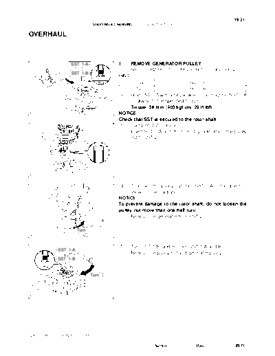
                          SST 1-A                   1.       REMOVE GENERATOR PULLEY
                                                             SST 09820-63010 (09820-06010, 09820-06020)
                          SST 1-B
                                                    HINT:
                   Turn                                   SST 1-A and B                 09820 - 06010
                                                             SST 2                      09820 - 06020
                                                    (a) Hold SST 1-A with a torque wrench, and tighten SST 1-B
                                       Hold
                                                        clockwise to the specified torque.
                                                        Torque: 39 Nm (400 kgfcm, 29 ftlbf)
                                           A81658   NOTICE:
                                                    Check that SST is secured to the rotor shaft.
                                                    (b) Clamp SST 2 in a vise.
                                                    (c) Insert SST 1-A and B into SST 2, and attach the pulley
                                                        nut to SST 2.
                            SST 2
          Insert


                                      SST 1
                                           A81659


                                                    (d)  To loosen the pulley nut, turn SST 1-A in the direction
                                                         shown in the illustration.
                                                    NOTICE:
                                                    To prevent damage to the rotor shaft, do not loosen the
                                                    pulley nut more than one-half turn.
                                                    (e) Remove the generator from SST 2.
                                    SST1-A

                            Turn
                                           A81660


                                                    (f)      Turn SST 1-B, and remove SST 1-A and B.
               SST 1-A
                                                    (g)      Remove the pulley nut and generator pulley.
               SST 1-B


                                    Turn
   Hold


                                           A81661


2005 SIENNA REPAIR MANUAL (RM1163U)

                                                                          Author :          Date :         2571
19-22
                               STARTING & CHARGING     -   GENERATOR ASSY

                                               2.    REMOVE GENERATOR REAR END COVER
                                               (a)   Place the generator on the generator pulley.
       Generator                               (b)   Remove the 3 nuts and the generator rear end cover.
       Pulley


                                      A81662


                                               3.    REMOVE TERMINAL INSULATOR
                                               (a)   Remove the terminal insulator from the generator rectifier
                                                     end frame.


                                      A81146


                                               4.    REMOVE GENERATOR BRUSH HOLDER ASSY
                                               (a)   Remove the 2 screws and the generator brush holder.


                                      A81147


                                               5.    REMOVE GENERATOR RECTIFIER END FRAME
                                               (a)   Remove the 4 bolts.


                                      A81148


                                               (b)   Using SST, remove the generator rectifier end frame.
                                  Turn               SST 09950-4001 1 (09951-04020, 09952-04010,
          SST
                                                            09953-04020, 09954-04010, 09955-04071,
                                                            09957-04010, 09958-04011)


Hold

                                      A81663


2005 SIENNA REPAIR MANUAL (RM1163U)

                                                                 Author :             Date :              2572
                                                                                                             19-23
                                 STARTING & CHARGING      -   GENERATOR ASSY

   Generator Washer                              6.    REMOVE GENERATOR ROTOR ASSY
                                                 (a)   Remove the generator washer and the generator rotor.


                                        A81664


                                                 7.     INSPECT GENERATOR BRUSH HOLDER ASSY
                                                 (a)    Check the brush length.
                                                        (1) Using vernier calipers, measure the exposed brush
     Length
                                                             length.
                                                        Standard exposed brush length:
                                                        10.5 mm (0.413 in.)
                                                        Minimum exposed brush length: 4.5 mm (0.177 in.)
                                                 If the exposed brush length is less than minimum, replace the
                                        A79305   generator brush holder.

                                                 8.    INSPECT GENERATOR ROTOR ASSY
                                                 (a) Check the bearing is not rough or worn.
                                                 If necessary, replace the generator rotor.


                                        A79306


                                                 (b)    Check the rotor for open circuit.
         Slip Ring
                                                        (1) Using an ohmmeter, measure the resistance be-
                                                              tween the slip ring.
                                                        Resistance:
                                                        2.3 to 2.7  at 20_C (68_F) for 130A
                                                        1.5 to 1.9  at 20_C (68_F) for 150A
                                                 If the resistance is not as specified, replace the generator rotor.
                    Continuity
                                        A81665


                                                 (c)    Check the rotor for ground.
        Slip Ring          Rotor Core
                                                        (1) Using an ohmmeter, check that there is no continu-
                                                              ity between the slip ring and the rotor core.
                                                 If there is continuity, replace the generator rotor.
                                                 (d) Inspect slip rings.
                                                        (1) Check that the slip rings are not rough or scored.
                                                 If rough or scored, replace the generator rotor.
                     No Continuity
                                        A81666


2005 SIENNA REPAIR MANUAL (RM1163U)

                                                                   Author :              Date :               2573
19-24
                               STARTING & CHARGING     -   GENERATOR ASSY

                                               (e)    Check the slip ring diameter.
                                                      (1) Using vernier calipers, measure the slip ring diame-
    Diameter                                                ter.
                                                      Standard diameter:
                                                      14.2 to 14.4 mm (0.559 to 0.567 in.)
                                                      Minimum diameter: 14.0 mm (0.551 in.)
                                               If the diameter is less than minimum, replace the generator ro-
                                               tor.
                                      A75676


                                               9.    INSPECT GENERATOR DRIVE END FRAME BEARING
                                               (a) Check the bearing is not rough or worn.
                                               If necessary, replace the bearing.


                                      A81155


                                               10.   REMOVE GENERATOR DRIVE END FRAME BEARING
                                               (a)   Remove the 4 screws and the retainer plate.


                                      A81156


                                               (b)   Using SST, tap out the bearing.
                                                     SST 09950-60010 (09951-00250), 09950-70010
                                                            (09951-07100)
 Wooden
                            SST
 Block


                                      A81667


                                               11.   INSTALL GENERATOR DRIVE END FRAME BEARING
                                               (a)   Using SST and a press, press in a new bearing.
                            SST                      SST 09950-60010 (09951-00470), 09950-70010
                                                            (09951-07100)


                                      A81668


2005 SIENNA REPAIR MANUAL (RM1163U)

                                                                 Author :             Date :             2574
                                                                                                      19-25
                               STARTING & CHARGING     -   GENERATOR ASSY

                                               (b)   Install the retainer plate with the 4 screws.
                                                     Torque: 2.6 Nm (27 kgfcm, 23 in.lbf)


                                      A81156


         Generator Washer                      12.   INSTALL GENERATOR ROTOR ASSY
                                               (a)   Place the generator drive end frame on the generator
 Generator                                           pulley.
 Pulley                                        (b)   Install the generator rotor and the generator washer.


                                      A81670


                                               13.   INSTALL GENERATOR RECTIFIER END FRAME
                            Deep Socket
                            Wrench 21          (a)   Using deep socket wrench 21 and a press, press in the
                                                     generator rectifier end frame carefully.


                                      A81671


                                               (b)   Tighten the 4 bolts.
                                                     Torque: 5.8 Nm (59 kgfcm, 51 in.lbf)


                                      A81148


    Pin (1.0 mm (0.039 in.))                   14.   INSTALL GENERATOR BRUSH HOLDER ASSY
                                               (a)   While pushing the 2 brushes to inside the brush holder,
                                                     insert a pin (1.0 mm (0.039 in.)) into the brush holder
                                                     hole.


                                      A79315


2005 SIENNA REPAIR MANUAL (RM1163U)

                                                                 Author :             Date :          2575
19-26
                                STARTING & CHARGING        -    GENERATOR ASSY


                 Pin (1.0 mm (0.039 in.))      (b)      Install the generator brush holder with the 2 screws.
                                                        Torque: 1.8 Nm (18 kgfcm, 16 in.lbf)
                                               (c)      Pull out the pin (1.0 mm (0.039 in.)) from the generator
                                                        brush holder.


                                      A81672


                                               15.    INSTALL TERMINAL INSULATOR
                                               (a)    Install the terminal insulator to the generator rectifier end
                                                      frame.
                                               NOTICE:
                                               pay attention the mounting orientation of the terminal insu-
                                               lator.


                                      A81146


                                               16.      INSTALL GENERATOR REAR END COVER
                                               (a)      Install the generator rear end cover with the 3 nuts.
                                                        Torque: 4.6 Nm (47 kgfcm, 41 in.lbf)


                                      A81164


                      SST 1-A                  17.      INSTALL GENERATOR PULLEY
                                                        SST 09820-63010 (09820-06010, 09820-06020)
                      SST 1-B
                                               HINT:
               Turn                                  SST 1-A and B                   09820 - 06010
                                                        SST 2                        09820 - 06020
                                               (a) Install the generator pulley to the rotor shaft by tightening
                                  Hold
                                                   the pulley nut by hand.
                                               (b) Hold SST 1-A with a torque wrench, and tighten SST 1-B
                                      A81658       clockwise to the specified torque.
                                                   Torque: 39 Nm (400 kgfcm, 29 ftlbf)
                                               NOTICE:
                                               Check that SST is secured to the rotor shaft.


2005 SIENNA REPAIR MANUAL (RM1163U)

                                                                      Author :            Date :                2576
                                                                                                          19-27
                                  STARTING & CHARGING    -   GENERATOR ASSY

                                                 (c)   Clamp SST 2 in a vise.
                                                 (d)   Insert SST 1-A and B into SST 2, and attach the pulley
                                                       nut to SST 2
                         SST 2
          Insert


                                   SST 1
                                        A81659


                                                 (e)   Tighten the pulley nut by turning SST 1-A in the direction
                                                       shown in the illustration.
                                                       Torque: 111 Nm (1,125 kgfcm, 81 ftlbf)
                                                 (f)   Remove the generator from SST 2.


                                SST1-A

                         Turn
                                        A81673


                                                 (g)   Turn SST 1-B, and remove SST 1-A, B.
               SST 1-A
                                                 (h)   Turn the generator pulley, and check that the generator
               SST 1-B                                 pulley moves smoothly.


                                 Turn
   Hold


                                        A81661


2005 SIENNA REPAIR MANUAL (RM1163U)

                                                                  Author :             Date :              2577


◦ Jabse Service Manual Search 2026 ◦ Jabse PravopisonTap.bg ◦ Other service manual resources online : FixyaeServiceinfo