Service Manuals, User Guides, Schematic Diagrams or docs for : . Car Manuals Toyota Sienna 2004-2007 Approved SRM 19 2041al02 w040001

<< Back | Home

Most service manuals and schematics are PDF files, so You will need Adobre Acrobat Reader to view : Acrobat Download Some of the files are DjVu format. Readers and resources available here : DjVu Resources
For the compressed files, most common are zip and rar. Please, extract files with Your favorite compression software ( WinZip, WinRAR ... ) before viewing. If a document has multiple parts, You should download all, before extracting.
Good luck. Repair on Your own risk. Make sure You know what You are doing.


Image preview - the first page of the document
w040001


>> Download w040001 documenatation <<

Text preview - extract from the document
30-6                  DRIVE SHAFT / PROPELLER SHAFT     -   PROPELLER W/CENTER BEARING SHAFT
                                                            ASSY (4WD)
                                                                                                            3001T-04


OVERHAUL
HINT:
COMPONENTS: See page 30-5
1.    REMOVE EXHAUST PIPE ASSY (See page 15-6 )

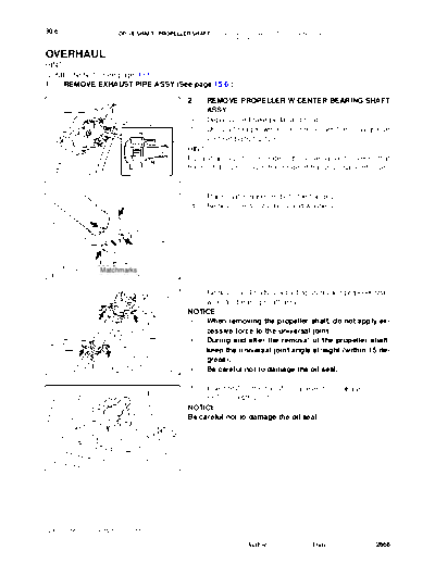
                                               2.    REMOVE PROPELLER W/CENTER BEARING SHAFT
                                                     ASSY
                                               (a)   Depress the brake pedal and hold it.
                                               (b)   Using a hexagon wrench (6 mm), loosen the cross groove
                                                     joint set bolts 1/2 turn.
                                               HINT:
                                               Put a shop rug into the inside of the universal joint cover so that
                                               the boot does not touch the inside of the universal joint cover.
 C23342                               F40503


                                               (c)   Place matchmarks on both the flanges.
                                               (d)   Remove the 4 nuts, bolts and washers.


                Matchmarks
                                      C92265


                                               (e) Remove the 4 bolts, 2 adjusting shims and propeller shaft
                                                   w/center bearing shaft assy.
                                               NOTICE:
                                                S  When removing the propeller shaft, do not apply ex-
                                                   cessive force to the universal joint.
                                                S  During and after the removal of the propeller shaft,
                                                   keep the universal joint angle straight (within 15 de-
                                                   grees).
                                      C83005    S  Be careful not to damage the oil seal.

                                               (f)  Insert SST in the transfer to prevent oil leakage.
                                  SST               SST 09325-20010
                                               NOTICE:
                                               Be careful not to damage the oil seal.


                                      F40505


2005 SIENNA REPAIR MANUAL (RM1163U)

                                                                  Author :              Date :                2668
                      DRIVE SHAFT / PROPELLER SHAFT    -   PROPELLER W/CENTER BEARING SHAFT              30-7
                                                           ASSY (4WD)

                                               3.    REMOVE PROPELLER SHAFT
                                               (a)   Place matchmarks on both the flanges.
                                               (b)   Remove the 4 nuts, bolts and washers.


           Matchmarks
                                      F40506


                                               4.   REMOVE INTERMEDIATE SHAFT
                                               (a)  Place matchmarks on the propeller shaft sub-assy and
                                                    universal joint flange.
                                               NOTICE:
                                               Do not punch the marks.
                                               (b) Using a hexagon wrench (6 mm), remove the 6 bolts and
                                                    2 washers and separate the intermediate shaft from the
                                                    rear propeller shaft.
         Matchmarks
C97592                                F44994


                                               5.    INSPECT SPIDER BEARING
                                               (a)   Check the spider bearing axial play by turning the flange
                                                     while holding the propeller shaft tightly.
                                               HINT:
                                               If necessary, replace the shaft.


                                      Q07980


                                               6.    INSPECT INTERMEDIATE SHAFT
                                               (a)   Using a dial indicator, check for the runout of the inter-
                                                     mediate shaft.
                                                     Maximum runout: 0.8 mm (0.031 in.)
                                               HINT:
                                               If the shaft runout exceeds the maximum, replace the shaft.
                                               NOTICE:
                                               The dial indicator must be set at right angles to the center
                                      C53258   of the intermediate shaft.

                                               (b)   Using a dial indicator, check the front side of the inter-
                                                     mediate shaft flange for the runout.
                                                     Maximum runout: 0.1 mm (0.004 in.)


                                      C53240


2005 SIENNA REPAIR MANUAL (RM1163U)

                                                                 Author :            Date :              2669
30-8                  DRIVE SHAFT / PROPELLER SHAFT     -   PROPELLER W/CENTER BEARING SHAFT
                                                            ASSY (4WD)

                                               (c)   Using a dial indicator, check the rear side of the intermedi-
                                                     ate shaft flange for the runout in the horizontal direction.
                                                     Maximum runout: 0.1 mm (0.004 in.)


                                      C53241


                                               (d)   Using a dial indicator, check the rear side of the intermedi-
                                                     ate shaft flange for the runout in the vertical direction.
                                                     Maximum runout: 0.1 mm (0.004 in.)
                                               HINT:
                                               If the intermediate shaft flange runout exceeds the maximum,
                                               replace the intermediate shaft.


                                      C53244


                                               7.    INSPECT PROPELLER SHAFT
                                               (a)   Using a dial indicator, check for the runout of the propeller
                                                     shaft.
                                                     Maximum runout: 0.8 mm (0.031 in.)
                                               HINT:
                                               If the shaft runout exceeds the maximum, replace the propeller
                                               shaft.
                                               NOTICE:
                                      C36277   The dial indicator must be set at right angles to the center
                                               of the propeller shaft.
                                               8.     REMOVE CENTER SUPPORT BEARING ASSY NO.2
          SST                                  (a) Using a chisel and a hammer, loosen the staked part of
                                                      the nut.
                                               (b) Using SST to hold the front flange, remove the nut and
                                                      plate washer.
   Hold                                               SST 09330-00021


                      Turn
                                      F40508


                                               (c)   Place matchmarks on the rear flange and shaft.


            Matchmarks                F40509


2005 SIENNA REPAIR MANUAL (RM1163U)

                                                                  Author :              Date :               2670
                          DRIVE SHAFT / PROPELLER SHAFT   -   PROPELLER W/CENTER BEARING SHAFT               30-9
                                                              ASSY (4WD)

                                                  (d)  Using SST, remove the rear flange.
                                                       SST 09950- 40011 (09951- 04020, 09952- 04010,
                                                              09953- 04030, 09954- 04010, 09955- 04061,
Hold                                                          09957-04010, 09958-04011)
                                                  NOTICE:
                                                  Be careful not to damage the universal joint flange.
                                                  (e) Remove the center support bearing assy No.2 and plate
                                                       washer.
                Turn        SST
                                        F40510


                                                  9.    REMOVE CENTER SUPPORT BEARING ASSY NO.1
                                    SST           (a)   Using a chisel and a hammer, loosen the staked part of
                                                        the nut.
                                                  (b)   Using SST to hold the front flange, remove the nut and
                                                        plate washer.
                                                        SST 09330-00021


                   Turn
         Hold                            F40511


                                                  (c)   Place matchmarks on the front flange and shaft.


                 Matchmarks             F40512


                                                  (d)  Using SST, remove the front flange.
           SST                                         SST 09950- 40011 (09951- 04020, 09952- 04010,
                                                              09953- 04030, 09954- 04010, 09955- 04061,
Hold                                                          09957-04010, 09958-04011)
                                                  NOTICE:
                                                  Be careful not to damage the universal joint flange.
                                                  (e) Remove the center support bearing assy No.1 and plate
                                                       washer.
            Turn
C23354                                  F40513


                                                  10.   INSPECT CENTER SUPPORT BEARING ASSY NO.2
                                                  (a)   Turn the bearing by hand with applying force in the direc-
                                                        tion of rotating. Check the bearing turns smoothly.
                                                  (b)   Check that the seals and bracket are not cracked or dam-
                                                        aged.
                                                  HINT:
                                                  If the bearing is damaged, worn, or does not turn freely, replace
                                                  it.
                                        C22188


2005 SIENNA REPAIR MANUAL (RM1163U)

                                                                    Author :             Date :              2671
30-10                     DRIVE SHAFT / PROPELLER SHAFT   -   PROPELLER W/CENTER BEARING SHAFT
                                                              ASSY (4WD)

11.     INSPECT CENTER SUPPORT BEARING ASSY NO.1
(a)     Inspect the center support bearing assy No.1 by the same procedures as the center support bearing
        assy No.2.


                                                 12.   INSPECT PROPELLER SHAFT
                                                 (a)   Using a dial indicator, check for the runout of the rear pro-
                                                       peller shaft.
                                                       Maximum runout: 0.8 mm (0.031 in.)
                                                 HINT:
                                                 If the shaft runout exceeds the maximum, replace the rear pro-
                                                 peller shaft.
                                                 NOTICE:
                                        C53259   The dial indicator must be set at right angles to the center
                                                 of the propeller shaft.
                                                 13. INSTALL CENTER SUPPORT BEARING ASSY NO.1
                                                 (a) Set the center support bearing assy No.1 on the inter-
                                                        mediate shaft, as shown in the illustration.
                                                 (b) Install a new washer to the intermediate shaft.
 Front                                           NOTICE:
                                                 Be sure to install the bearing in the correct direction.


                                        F40522


                                                 (c)   Align the matchmarks on the front flange and shaft, and
                                                       place the flange on the shaft.


                  Matchmarks            F40512


                                                 (d)   Using SST to hold the front flange, press the center sup-
                                                       port bearing assy No.1 into the position by tightening
                   Turn                                down a new nut and plate washer.
                                                       SST 09330-00021
                                                       Torque: 181 N


◦ Jabse Service Manual Search 2026 ◦ Jabse PravopisonTap.bg ◦ Other service manual resources online : FixyaeServiceinfo