Service Manuals, User Guides, Schematic Diagrams or docs for : . Car Manuals Toyota Sienna 2004-2007 Approved SRM 19 2041bl02 w040001

<< Back | Home

Most service manuals and schematics are PDF files, so You will need Adobre Acrobat Reader to view : Acrobat Download Some of the files are DjVu format. Readers and resources available here : DjVu Resources
For the compressed files, most common are zip and rar. Please, extract files with Your favorite compression software ( WinZip, WinRAR ... ) before viewing. If a document has multiple parts, You should download all, before extracting.
Good luck. Repair on Your own risk. Make sure You know what You are doing.


Image preview - the first page of the document
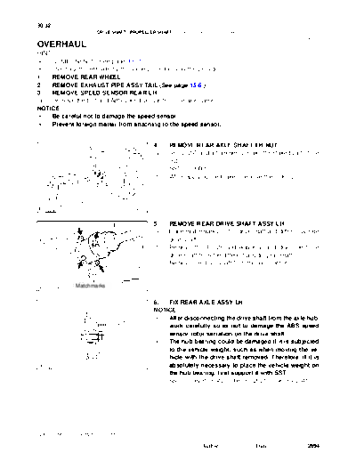
w040001


>> Download w040001 documenatation <<

Text preview - extract from the document
30-32
                      DRIVE SHAFT / PROPELLER SHAFT    -   REAR DRIVE SHAFT (4WD)
                                                                                                        300JB-02


OVERHAUL
HINT:
S   COMPONENTS: See page 30-31
S   Overhaul the RH side by the same procedures as the LH side.
1.  REMOVE REAR WHEEL
2.  REMOVE EXHAUST PIPE ASSY TAIL (See page 15-6 )
3.  REMOVE SPEED SENSOR REAR LH
(a) Remove the bolt and ABS speed sensor from the axle carrier.
NOTICE:
 S  Be careful not to damage the speed sensor.
 S  Prevent foreign matter from attaching to the speed sensor.


                                               4.    REMOVE REAR AXLE SHAFT LH NUT
                                               (a)   Using SST and a hammer, unstake the staked part of the
                                                     nut.
                                                     SST 09930-00010
                                               (b)   While applying the brakes, remove the lock nut.


             SST
    C89299                            F45049


                                               5.    REMOVE REAR DRIVE SHAFT ASSY LH
                                               (a)   Place matchmarks on the drive shaft and differential side
                                                     gear shaft.
                                               (b)   Remove the 4 nuts and washers, and disconnect the
                                                     drive shaft from the differential side gear shaft.
                                               (c)   Remove the drive shaft from the axle carrier.


              Matchmarks              C97746


                                               6.  FIX REAR AXLE ASSY LH
                                               NOTICE:
                                                S  After disconnecting the drive shaft from the axle hub,
                             SST                   work carefully so as not to damage the ABS speed
                                                   sensor rotor serration on the drive shaft.
                                                S  The hub bearing could be damaged if it is subjected
                                                   to the vehicle weight, such as when moving the ve-
                                                   hicle with the drive shaft removed. Therefore, if it is
    C66030                            F45050       absolutely necessary to place the vehicle weight on
                                                   the hub bearing, first support it with SST.
                                                   SST 09608-16042 (09608-02021, 09608-02041)


2005 SIENNA REPAIR MANUAL (RM1163U)

                                                                  Author :            Date :              2694
                                                                                                          30-33
                         DRIVE SHAFT / PROPELLER SHAFT   -   REAR DRIVE SHAFT (4WD)

                                                7.    INSPECT REAR DRIVE SHAFT ASSY LH
                                                (a)   Check that there is no remarkable play in the radial direc-
                                                      tion of the outboard joint.
                                                (b)   Check that the inboard joint slides smoothly in the thrust
                                                      direction.
                                                (c)   Check that there is no remarkable play in the radial direc-
                                                      tion of the inboard joint.
                                                (d)   Check the boots for damage.
                                       Z12871


                                                8.    SEPARATE REAR DRIVE SHAFT INBOARD JOINT
                                                      BOOT NO.2 CLAMP
                                                (a)   Using a screwdriver, remove the inboard joint boot No.2
                                                      clamp.
                                                (b)   Remove the inboard joint boot clamp by the same proce-
                                                      dures as the inboard joint boot No.2 clamp.


                                       C68602


9.       SEPARATE RR DRIVE SHAFT INBORD JOINT BOOT
(a)      Remove the inboard joint boot from the inboard joint assy.


                  Matchmarks                    10.  REMOVE REAR DRIVE SHAFT INBOARD JOINT
                                                     ASSY
                                                (a) Remove the circlip, place matchmarks on the inboard
                                                     joint assy and outboard joint shaft.
                                                NOTICE:
                                                Do not punch the marks.
                                                (b) Pull out the inboard joint assy.
                                                NOTICE:
      C92515                           F45462   Be careful not to drop the balls.

                                                (c) Place matchmarks on the outboard joint shaft, inner race
                               Matchmarks
                                                     and cage.
                                                NOTICE:
                                                Do not punch the marks.
                                                (d) Remove the 6 bolts.
                                                (e) Slide the cage toward outboard joint.


  C66027                               F45464


 2005 SIENNA REPAIR MANUAL (RM1163U)

                                                                   Author :            Date :              2695
30-34
                      DRIVE SHAFT / PROPELLER SHAFT     -   REAR DRIVE SHAFT (4WD)

                                               (f)   Using a snap ring expander, remove the snap ring.


  C66028                              F45463


                                               (g)   Using a brass bar and hammer, remove the inner race.
                                               (h)   Remove the cage.
                                               (i)   Remove the inboard joint boot, inboard joint boot clamp
                                                     and inboard joint boot No.2 clamp.


                                      C66029


                                               11.   SEPARATE REAR DRIVE SHAFT OUTBOARD JOINT
                                                     BOOT NO. 2 CLAMP
                                               (a)   Using pliers, remove the outboard joint boot No.2 clamp.
                                               (b)   Remove the outboard joint boot clamp by the same pro-
                                                     cedures as the outboard joint boot No.2 clamp.


                                      C81167


12. REMOVE RR DRIVE SHAFT OUTBORD JOINT BOOT
(a) Remove the outboard joint boot from the outboard joint shaft assy.
(b) Remove the old grease from the outboard joint.
NOTICE:
Do not disassemble the outboard joint.

                                               13. INSTALL RR DRIVE SHAFT OUTBORD JOINT BOOT
                                               HINT:
                             Vinyl Tape
                                               Before installing the boots, wrap the spline of the outboard joint
                                               shaft with vinyl tape to prevent the boots from being damaged.
                                               (a) Install the outboard joint boot, 2 outboard joint boot
                                                     clamps.
                                               (b) Before assembling the boots, pack the outboard joint and
                                                     boot with grease in the boot kit.
                                      RA1310         Grease capacity: 90 - 110 g (3.2 - 3.9 oz.)
                                               (c) Make sure that the 2 boots are on the shaft groove.


2005 SIENNA REPAIR MANUAL (RM1163U)

                                                                   Author :            Date :               2696
                                                                                                          30-35
                      DRIVE SHAFT / PROPELLER SHAFT      -   REAR DRIVE SHAFT (4WD)


                                 Hold            14.  INSTALL REAR DRIVE SHAFT OUTBOARD JOINT
      SST                                             BOOT NO. 2 CLAMP
                                                 (a) Hold the drive shaft in a soft vise.
                                                 (b) Secure the 2 outboard joint boot clamps onto the boot.
                                                 (c) Place SST onto the outboard joint large boot clamp.
                                                      SST 09521-24010
                                                 (d) Tighten the SST so that the large clamp is pinched.
                                                 NOTICE:
                          Turn          R10425   Do not overtighten the SST.

                                                 (e)   Using SST, adjust the clearance of the large clamp.
                                                       SST 09240-00020
                                                       Clearance: 1.2 - 4.0 mm (0.047 - 0.157 in.)
                                                 (f)   Install the outboard joint boot clamp by the same proce-
                                                       dures as the outboard joint boot No.2 clamp.

SST


                                        R10426


                                                 15.   INSTALL REAR DRIVE SHAFT INBOARD JOINT ASSY
                                                 (a)   Through a new inboard joint boot, 2 new inboard joint
                                                       clamps and cage.
                                                 (b)   Align the matchmarks, using a brass bar and a hammer,
                                                       install the inner race.


                                        D27471


                                                 (c)   Using a snap ring expander, install a new rear drive shaft
                                                       snap ring.


 C66028                                 F45463


                                                 (d)   Align the matchmarks, install the cage to the inner race.
                                                 (e)   Install the 6 balls with grease to the inner race.
                         Matchmarks              (f)   Pack the inboard joint shaft and boot with grease in the
                                                       boot kit.
                                                       Grease capacity: 130 - 150g (4.6 - 5.3 oz.)


  C66027                                F45464


2005 SIENNA REPAIR MANUAL (RM1163U)

                                                                   Author :            Date :              2697
30-36
                          DRIVE SHAFT / PROPELLER SHAFT   -   REAR DRIVE SHAFT (4WD)

                                                  (g)   Align the matchmarks, install the inboard joint assy to the
                Matchmarks
                                                        outboard joint shaft assy.
                                                  (h)   Install the circlip.


  C92515                                 F45462


16.     INSTALL RR DRIVE SHAFT INBORD JOINT BOOT
(a)     Install the inboard joint boot to the inboard joint assy.


                                                  17.   INSTALL REAR DRIVE SHAFT INBOARD JOINT BOOT
                                                        NO.2 CLAMP
                                                  (a)   Using a screwdriver, install the inboard joint boot No.2
                                                        clamp.
                                                  (b)   Install the inboard joint boot clamp by the same proce-
                                                        dures as the inboard joint boot No.2 clamp.


                                        C83043


                                                  18.   INSPECT REAR DRIVE SHAFT ASSY LH
                                                  (a)   Check that there is no remarkable play in the radial direc-
                                                        tion of the outboard joint.
                                                  (b)   Check that the inboard joint slides smoothly in the thrust
                                                        direction.
                                                  (c)   Check that there is no remarkable play in the radial direc-
                                                        tion of the inboard joint.
                                                  (d)   Check the boots for damage.
                                         Z12871


                                                  (e)   Make sure that the 2 boots are not stretched or contracted
                                                        when the drive shaft is at standard length.
                                                        Standard length: 704.8 


◦ Jabse Service Manual Search 2026 ◦ Jabse PravopisonTap.bg ◦ Other service manual resources online : FixyaeServiceinfo