Service Manuals, User Guides, Schematic Diagrams or docs for : . Car Manuals Toyota Sienna 2004-2007 Approved SRM 12 20pzh x040001
<< Back | HomeMost service manuals and schematics are PDF files, so You will need Adobre Acrobat Reader to view : Acrobat Download Some of the files are DjVu format. Readers and resources available here : DjVu Resources
For the compressed files, most common are zip and rar. Please, extract files with Your favorite compression software ( WinZip, WinRAR ... ) before viewing. If a document has multiple parts, You should download all, before extracting.
Good luck. Repair on Your own risk. Make sure You know what You are doing.
Image preview - the first page of the document
>> Download x040001 documenatation <<
Text preview - extract from the document
17-1 1
LUBRICATION - OIL PUMP ASSY
170FH-01
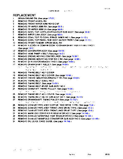
REPLACEMENT
1. DRAIN ENGINE OIL (See page 17-23 )
2. REMOVE FRONT WHEEL RH
3. REMOVE FRONT WIPER ARM HEAD CAP
4. REMOVE FR WIPER ARM RH (See page 66-8 )
5. REMOVE FR WIPER ARM LH (See page 66-8 )
6. REMOVE COWL TOP VENTILATOR LOUVER SUB-ASSY (See page 66-8 )
7. REMOVE WIPER LINK ASSY (See page 66-8 )
8. REMOVE COWL TOP TO COWL BRACE INNER NO.1 (See page 11-13 )
9. REMOVE COWL TOP PANEL SUB-ASSY OUTER FRONT (See page 11-13 )
10. REMOVE FRONT FENDER APRON SEAL RH
11. REMOVE V (COOLER COMPRESSOR TO CRANKSHAFT PULLEY) BELT NO.1
(See page 14-5 )
12. REMOVE GENERATOR ASSY (See page 19-19 )
13. REMOVE VANE PUMP V BELT (See page 14-5 )
14. REMOVE ENGINE MOVING CONTROL ROD (See page 14-84 )
15. REMOVE ENGINE MOUNTING STAY NO.2 RH (See page 14-84 )
16. REMOVE GENERATOR BRACKET NO.2 (See page 14-84 )
17. REMOVE CRANKSHAFT PULLEY (See page 14-84 )
SST 09213-54015 (91651-60855), 09330-00021, 09950-50013 (09951-05010, 09952-05010,
09953-05020, 09954-05031)
18. REMOVE TIMING BELT NO.1 COVER
19. REMOVE TIMING BELT NO.2 COVER (See page 14-84 )
20. REMOVE ENGINE MOUNTING BRACKET RH (See page 14-84 )
21. REMOVE TIMING BELT GUIDE NO.2
22. REMOVE TIMING BELT (See page 14-84 )
23. REMOVE TIMING BELT IDLER SUB-ASSY NO.2
24. REMOVE CAMSHAFT TIMING PULLEY (See page 14-99 )
SST 09960-10010 (09962-01000, 09963-01000), 09249-63010
25. REMOVE TIMING BELT NO.3 COVER (See page 14-99 )
26. REMOVE TIMING BELT IDLER SUB-ASSY NO.1 (See page 16-13 )
27. REMOVE CRANKSHAFT TIMING PULLEY (See page 14-152 )
SST 09950-50013 (09951-05010, 09952-05010, 09953-05020, 09954-05011)
28. REMOVE EXHAUST PIPE ASSY CENTER (4WD DRIVE TYPE) (See page 15-6 )
29. REMOVE EXHAUST PIPE ASSY FRONT (2WD DRIVE TYPE) (See page 15-2 )
30. REMOVE EXHAUST PIPE ASSY FRONT (4WD DRIVE TYPE) (See page 15-6 )
31. REMOVE MANIFOLD CONVERTER INSULATOR NO.3 (See page 14-146 )
32. REMOVE EXHAUST MANIFOLD HEAT INSULATOR NO.2 (See page 14-146 )
33. REMOVE EXHAUST MANIFOLD CONVERTER SUB-ASSY NO.2 (See page 14-146 )
34. REMOVE OIL LEVEL GAGE GUIDE (See page 14-146 )
2005 SIENNA REPAIR MANUAL (RM1163U)
Author : Date : 2532
17-12
LUBRICATION - OIL PUMP ASSY
35. REMOVE GENERATOR BELT ADJUSTING BAR
(a) Remove the 2 bolts, the 2 nuts and the adjusting bar.
A52889
36. SEPARATE COMPRESSOR AND MAGNETIC CLUTCH
(a) Disconnect the compressor connector.
(b) Remove the 4 bolts, the adjusting bar bracket and the
compressor.
HINT:
The hoses are off to the side instead of detaching.
Adjusting Bar Bracket A78377
37. REMOVE COMPRESSOR MOUNTING BRACKET
NO.1
(a) Remove the 2 bolts and the compressor mounting brack-
et No. 1.
A36749
38. SEPARATE ENGINE MOUNTING INSULATOR RR
(4WD DRIVE TYPE)
(a) Remove the 2 nuts and disconnect the engine mounting
insulator RR.
A52017
2005 SIENNA REPAIR MANUAL (RM1163U)
Author : Date : 2533
17-13
LUBRICATION - OIL PUMP ASSY
39. SEPARATE ENGINE MOUNTING INSULATOR FR
(a) Remove the 4 nuts and separate the engine mounting in-
sulator FR.
NOTICE:
Do not remove the engine mounting insulator FR.
40. REMOVE ENGINE MOUNTING INSULATOR RH
(a) Remove the bolt and disconnect the power steering re-
turn hose cramp from the frame.
A78378
(b) Remove the 4 nuts.
(c) Place a wooden block on a jack underneath the engine.
(d) Jack-up the engine and remove the engine mounting in-
sulator RH.
NOTICE:
Be careful not to damage the oil pan.
A52016
41. REMOVE ENGINE MOUNTING BRACKET RH
(a) Remove the 4 bolts, the nut and the bracket.
A52015
42. REMOVE OIL PAN SUB-ASSY NO.2
(a) Remove the 10 bolts and the 2 nuts.
A36750
2005 SIENNA REPAIR MANUAL (RM1163U)
Author : Date : 2534
17-14
LUBRICATION - OIL PUMP ASSY
(b) Insert the blade of SST between oil pan No.1 and oil pan
SST No.2, cut off the sealer and remove the oil pan No.2.
SST 09032-00100
NOTICE:
S Be careful not to damage the contact surface of oil
pan No. 1 where oil pan No. 2 is mounting.
SST S Do not damage flange portion of oil pan No. 2 when re-
moving.
A00019
43. REMOVE OIL STRAINER SUB-ASSY
(a) Remove the bolt, the 2 nuts, the oil strainer and the gasket.
44. REMOVE OIL PAN SUB-ASSY
(a) Remove the 2 bolts and the flywheel housing under cover.
A78379
(b) Loosen and remove the 17 bolts and the 2 nuts uniformly.
A36754
(c) Using a screwdriver, remove the oil pan by prying be-
tween the cylinder block and the oil pan.
NOTICE:
Be careful not to damage the contact surfaces of the oil pan
and cylinder block.
B04137
45. REMOVE CRANKSHAFT POSITION SENSOR
(a) Disconnect the crankshaft position sensor connector.
(b) Remove the bolt and the crankshaft position sensor.
2005 SIENNA REPAIR MANUAL (RM1163U)
Author : Date : 2535
17-15
LUBRICATION - OIL PUMP ASSY
46. REMOVE OIL PUMP ASSY
(a) Remove the 9 bolts.
(b) Using a screwdriver, remove the oil pump by prying be-
tween the oil pump and the main bearing cap.
(c) Remove the O-ring.
A51990
47. INSTALL OIL PUMP SEAL
SST (a) Using SST and a hammer, tap in a new oil seal until its sur-
face is flush with the oil pump body edge.
SST 09223-00010
NOTICE:
S Be careful not to tap the oil seal at an angle.
S Keep the lip free of foreign objects.
(b) Apply MP grease to the oil seal lip.
A78754 48. INSTALL OIL PUMP ASSY
(a) Remove any old seal packing material from the contact
surface.
(b) Apply a light coat of engine oil to a new O-ring and place
it on the cylinder block.
A36784
2005 SIENNA REPAIR MANUAL (RM1163U)
Author : Date : 2536
17-16
LUBRICATION - OIL PUMP ASSY
(c) Apply a continuous bead of seal packing (Diameter 2 to
3 mm (0.08 to 0.12 in.)) as shown in the illustration.
B
Seal packing: Part No. 08826-00080 or equivalent
NOTICE:
A S Remove any oil from contact surface.
S Apply seal packing to the inner side of the bolt holes.
S Install the oil pump within 3 minutes after applying
C seal packing.
S Do not expose the seal to engine oil within 2 hours af-
ter installing.
Seal Packing
A
Seal Width
B
2 to 3 mm
C
A78725
(d) Align the key of the oil pump drive gear with the keyway
located on the crankshaft, and slide the oil pump into
place.
A36785
(e) Install the oil pump with the 9 bolts. Tighten the bolts uni-
A
B formly in several steps.
C A
A Torque:
Bolt A 8.0 Nm (82 kgfcm, 71 in.lbf)
Bolt B 20 Nm (199 kgfcm, 14 ftlbf)
B Bolt C 43 Nm (439 kgfcm, 32 ftlbf)
A
A A
A51990
49. INSTALL CRANKSHAFT POSITION SENSOR
Torque: 8.0 Nm (80 kgfcm, 71 in.lbf)
50. INSTALL OIL PAN SUB-ASSY
(a) Remove any old seal packing from the contact surface.
2005 SIENNA REPAIR MANUAL (RM1163U)
Author : Date : 2537
17-17
LUBRICATION - OIL PUMP ASSY
(b)
Apply a continuous bead of seal packing (Diameter 3 to
4 mm (0.12 to 0.16 in.)) as shown in the illustration.
Region "X" Region "Y" Seal packing: Part No. 08826-00080 or equivalent
NOTICE:
S Remove any oil from the contact surface.
S Apply seal packing to the outer side of the bolt holes
in the region "X".
S Apply seal packing to the inner side of the bolt holes
in the region "Y".
S Install the oil pan within 3 minutes after applying seal
packing.
A B
S Do not expose the seal to engine oil within 2 hours af-
Seal Packing ter installing.
A B (c) Install the oil pan No.1 with the 17 bolts and the 2 nuts.
Tighten the bolts uniformly in several steps.
Torque:
10 mm head 8.0 Nm (82 kgfcm, 71 in.lbf)
Seal Width 12 mm head 20 Nm (199 kgfcm, 14 ftlbf)
3 to 4 mm
A78726 14 mm head 37 Nm (379 kgfcm, 27 ftlbf)
(d) Install the flywheel housing under cover with the 2 bolts.
Torque: 7.8 Nm (80 kgfcm, 69 in.lbf)
51. INSTALL OIL STRAINER SUB-ASSY
(a) Install a new gasket and the oil strainer with the bolt and the 2 nuts.
Torque: 8.0 Nm (82 kgfcm, 71 in.lbf)
52. INSTALL OIL PAN SUB-ASSY NO.2
(a) Remove any old seal packing from the contact surface.
(b) Apply a continuous bead of seal packing (Diameter 4 to
Seal Packing 5 mm (0.16 to 0.20 in.)) as shown in the illustration.
Seal packing: Part No. 08826-00080 or equivalent
NOTICE:
S Remove any oil from the contact surface.
S Apply seal packing to the inner side of the bolt holes.
S Install the oil pan within 3 minutes after applying seal
packing.
S Do not expose the seal to engine oil within 2 hours af-
ter installing.
(c) Install the oil pan No. 2 with the 10 bolts and the 2 nuts.
Torque: 8.0 Nm (82 kgfcm, 71 in.lbf)
A B
A
Seal Width
4 to 5 mm
B
A78727
2005 SIENNA REPAIR MANUAL (RM1163U)
Author : Date : 2538
17-18
LUBRICATION - OIL PUMP ASSY
53. INSTALL ENGINE MOUNTING BRACKET RH
A Torque:
C B Bolt A 54 Nm (551 kgfcm, 40 ftlbf)
Nut B 54 Nm (551 kgfcm, 40 ftlbf)
Bolt C 44 Nm (449 kgfcm, 32 ftlbf)
A
A
A78825
54. INSTALL ENGINE MOUNTING INSULATOR RH
A Torque:
Nut A 95 Nm (969 kgfcm, 70 ftlbf)
Nut B 87 Nm (887 kgfcm, 64 ftlbf)
B B B A78826
55. INSTALL ENGINE MOUNTING INSULATOR FR
A
Torque:
Nut A 87 Nm (887 kgfcm, 64 ftlbf)
Nut B 52 Nm (530 kgfcm, 38 ftlbf)
B
B
B
A78378
56. INSTALL ENGINE MOUNTING INSULATOR RR (4WD
DRIVE TYPE)
Torque: 52 Nm (530 kgfcm, 38 ftlbf)
A52017
2005 SIENNA REPAIR MANUAL (RM1163U)
Author : Date : 2539
17-19
LUBRICATION - OIL PUMP ASSY
57. INSTALL COMPRESSOR MOUNTING BRACKET NO.1
Torque: 25 Nm (250 kgfcm, 18 ftlbf)
58. INSTALL COMPRESSOR AND MAGNETIC CLUTCH
(a) Install the compressor and the adjusting bar bracket with
the 4 bolts.
Torque: 25 Nm (250 kgfcm, 18 ftlbf)
Adjusting Bar Bracket A78377
59. INSTALL GENERATOR BELT ADJUSTING BAR
A
(a) Install the adjusting bar with the 2 bolts and the 2 nuts.
Torque:
Nut A 43 Nm (438 kgfcm, 32 ftlbf)
Bolt B 18 Nm (184 kgfcm, 13 ftlbf)
Bolt C 8.4 Nm (85 kgfcm, 74 in.lbf)
C B
A78828
60. INSTALL OIL LEVEL GAGE GUIDE (See page 14-146 )
61. INSTALL EXHAUST MANIFOLD CONVERTER SUB-ASSY NO.2 (See page 14-146 )
62. INSTALL EXHAUST MANIFOLD HEAT INSULATOR NO.2 (See page 14-146 )
63. INSTALL MANIFOLD CONVERTER INSULATOR NO.3 (See page 14-146 )
64. INSTALL EXHAUST PIPE ASSY FRONT (2WD DRIVE TYPE) (See page 15-2 )
65. INSTALL EXHAUST PIPE ASSY FRONT (4WD DRIVE TYPE) (See page 15-6 )
66. INSTALL EXHAUST PIPE ASSY CENTER (4WD DRIVE TYPE) (See page 15-6 )
67. INSTALL CRANKSHAFT TIMING PULLEY (See page 14-152 )
68. INSTALL TIMING BELT IDLER SUB-ASSY NO.1 (See page 16-13 )
69. INSTALL TIMING BELT NO.3 COVER (See page 14-99 )
70. INSTALL CAMSHAFT TIMING PULLEY (See page 14-99 )
SST 09960-10010 (09962-01000, 09963-01000), 09249-63010
71. INSTALL TIMING BELT IDLER SUB-ASSY NO.2 (See page 14-99 )
72. INSPECT TIMING BELT (See page 14-84 )
73. INSTALL TIMING BELT (See page 14-84 )
SST 09960-10010 (09962-01000, 09963-01000)
74. INSTALL CHAIN TENSIONER ASSY NO.1 (See page 14-84 )
75. INSTALL TIMING BELT GUIDE NO.2 (See page 14-84 )
76. INSTALL ENGINE MOUNTING BRACKET RH (See page 14-84 )
77. INSTALL TIMING BELT NO.2 COVER (See page 14-84 )
78. INSTALL TIMING BELT NO.1 COVER (See page 14-84 )
79. INSTALL CRANKSHAFT PULLEY (See page 14-84 )
SST 09213-54015 (91651-60855), 09330-00021
80. INSTALL GENERATOR BRACKET NO.2 (See page 14-84 )
81. INSTALL ENGINE MOUNTING STAY NO.2 RH (See page 14-84 )
2005 SIENNA REPAIR MANUAL (RM1163U)
Author : Date : 2540
17-20
LUBRICATION - OIL PUMP ASSY
82. INSTALL ENGINE MOVING CONTROL ROD (See page 14-84 )
83. INSTALL VANE PUMP V BELT (See page 14-5 )
84. INSTALL GENERATOR ASSY (See page 19-19 )
85. INSTALL V (COOLER COMPRESSOR TO CRANKSHAFT PULLEY) BELT NO.1
(See page 14-5 )
86. INSPECT DRIVE BELT DEFLECTION AND TENSION (REFERENCE) (See page 14-1 )
87. INSTALL COWL TOP PANEL SUB-ASSY OUTER FRONT (See page 11-13 )
88. INSTALL COWL TOP TO COWL BRACE INNER NO.1 (See page 11-13 )
89. INSTALL WIPER LINK ASSY (See page 66-8 )
90. INSTALL FR WIPER ARM LH (See page 66-8 )
91. INSTALL FR WIPER ARM RH (See page 66-8 )
92. INSTALL FRONT WHEEL RH (See page 14-5 )
93. ADD ENGINE OIL (See page 17-23 )
94. CHECK FOR ENGINE OIL LEAKS
95. CHECK FOR EXHAUST GAS LEAKS
2005 SIENNA REPAIR MANUAL (RM1163U)
Author : Date : 2541
◦ Jabse Service Manual Search 2026 ◦ Jabse Pravopis ◦ onTap.bg ◦ Other service manual resources online : Fixya ◦ eServiceinfo