Service Manuals, User Guides, Schematic Diagrams or docs for : . Car Manuals Toyota Sienna 2004-2007 Approved SRM 25 20426 w040001
<< Back | HomeMost service manuals and schematics are PDF files, so You will need Adobre Acrobat Reader to view : Acrobat Download Some of the files are DjVu format. Readers and resources available here : DjVu Resources
For the compressed files, most common are zip and rar. Please, extract files with Your favorite compression software ( WinZip, WinRAR ... ) before viewing. If a document has multiple parts, You should download all, before extracting.
Good luck. Repair on Your own risk. Make sure You know what You are doing.
Image preview - the first page of the document
>> Download w040001 documenatation <<
Text preview - extract from the document
51-19
POWER STEERING - RACK & PINION POWER STEERING GEAR ASSY
OVERHAUL
NOTICE:
When installing , coat the parts indicated by the arrows with power steering fluid or molybdenum
disulfide lithium base grease (See page 51-16 ).
1. INSPECT CENTER FRONT WHEEL 510DA-02
2. REMOVE FRONT WHEEL
3. SEPARATE TIE ROD ASSY LH (See page 30-18 )
SST 09628-6201 1
4. SEPARATE TIE ROD ASSY RH
SST 09628-6201 1
HINT:
Perform the same procedure on the other side.
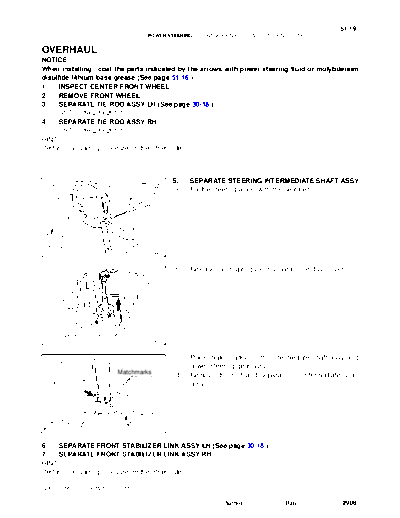
5. SEPARATE STEERING INTERMEDIATE SHAFT ASSY
(a) Fix the steering wheel with the seat belt.
D30613
(b) Release the 3 springs and separate the dust cover.
Spring
D30704
(c) Place matchmarks on the intermediate shaft assy and
power steering gear assy.
Matchmarks
(d) Remove the bolt and separate the intermediate shaft
assy.
D29986
6. SEPARATE FRONT STABILIZER LINK ASSY LH (See page 30-18 )
7. SEPARATE FRONT STABILIZER LINK ASSY RH
HINT:
Perform the same procedure on the other side.
2005 SIENNA REPAIR MANUAL (RM1163U)
Author : Date : 2908
51-20
POWER STEERING - RACK & PINION POWER STEERING GEAR ASSY
8. REMOVE FRONT STABILIZER BRACKET NO.1 LH
FF: (a) Remove the 2 bolts and remove the stabilizer bracket
No.1.
4WD:
D30615
9. REMOVE FRONT STABILIZER BRACKET NO.1 RH
HINT:
Perform the same procedure on the other side.
10. DISCONNECT PRESSURE FEED TUBE ASSY
(a) Remove the clip and disconnect the return tube assy from
the power steering gear assy.
D29970
(b) Using SST, disconnect the pressure feed tube assy from
the power steering gear assy.
SST 09023-12701
SST
D29971
2005 SIENNA REPAIR MANUAL (RM1163U)
Author : Date : 2909
51-21
POWER STEERING - RACK & PINION POWER STEERING GEAR ASSY
(c) Remove the bolt and separate the tube clamp.
D29974
(d) Remove the nut and separate the tube clamp.
D29975
11. REMOVE RACK & PINION POWER STEERING GEAR
ASSY
(a) Remove the 2 bolts, nuts and the power steering gear
assy.
NOTICE:
Do not damage the 2 pressure tubes.
D29979
12. REMOVE RETURN TUBE NO.2
SST (a) Using SST, remove the return tube No.2.
SST 09023-12701
D30600
SST 13. REMOVE STEERING LEFT TURN PRESSURE TUBE
(a) Using SST, remove the left turn pressure tube.
SST 09023-38201
(b) Remove the 2 O-rings from the left turn pressure tube.
O-ring D29981
2005 SIENNA REPAIR MANUAL (RM1163U)
Author : Date : 2910
51-22
POWER STEERING - RACK & PINION POWER STEERING GEAR ASSY
14. REMOVE STEERING RIGHT TURN PRESSURE TUBE
SST 09023-38201
HINT:
Perform the same procedure on the other side.
15. FIX RACK & PINION POWER STEERING GEAR ASSY
SST
(a) Using SST, secure the power steering gear assy.
SST 09612-00012
HINT:
Tape the SST before use.
F41498 D30616
16. REMOVE TIE ROD ASSY LH
(a) Place matchmarks on the tie rod assy and rack end sub-
assy.
(b) Loosen the lock nut, and remove the tie rod assy and lock
nut.
Matchmarks
F40050
17. REMOVE TIE ROD ASSY RH
HINT:
Perform the same procedure on the other side.
18. INSPECT TIE ROD ASSY LH
(a) Secure the tie rod assy in a vise.
(b) Install the nut to the stud bolt.
(c) Flip the ball joint stud back and forth 5 times.
(d) Using a torque wrench, turn the nut continuously at a rate
of 3 to 5 seconds per turn and take the torque reading on
the 5th turn.
Turning torque:
ZK8184 0.83 to 3.43 Nm (8.5 to 35.0 kgfcm, 7.3 to 30.4 in.lbf)
19. INSPECT TIE ROD ASSY RH
HINT:
Perform the same procedure on the other side.
20. REMOVE STEERING RACK BOOT CLIP
(a) Remove the 2 rack boot clips.
21. REMOVE STEERING RACK BOOT NO.2 CLAMP
(a) Using pliers, remove the rack boot No.2 clamp.
NOTICE:
Be careful not to damage the steering rack boot No.2.
2005 SIENNA REPAIR MANUAL (RM1163U)
Author : Date : 2911
51-23
POWER STEERING - RACK & PINION POWER STEERING GEAR ASSY
22. REMOVE STEERING RACK BOOT NO.1 CLAMP
HINT:
Perform the same procedure on the other side.
23. REMOVE STEERING RACK BOOT NO.2
24. REMOVE STEERING RACK BOOT NO.1
25. REMOVE STEERING RACK END SUB-ASSY
Claw (a) Using a screwdriver and a hammer, unstake the claw
Washer washer.
NOTICE:
Avoid any impact to the power steering rack.
C83166
(b) Using 2 SST, remove the 2 steering rack end sub-assy
and 2 claw washers.
SST 09922-10010
NOTICE:
S Use SST 09922-10010 in the direction shown in the il-
lustration.
SST
S Securely hold the power steering rack end with a SST.
SST
F41526
26. REMOVE RACK GUIDE
SST
(a) Using SST, remove the rack guide spring cap nut.
SST 09922-10010
NOTICE:
Use SST 09922-10010 in the direction shown in the illustra-
tion.
F41500
2005 SIENNA REPAIR MANUAL (RM1163U)
Author : Date : 2912
51-24
POWER STEERING - RACK & PINION POWER STEERING GEAR ASSY
(b) Using SST, remove the rack guide spring cap.
SST 09631-10021
(c) Remove the compression spring and the rack guide.
SST
F41501
Socket Wrench (27 mm) 27. REMOVE POWER STEERING CONTROL VALVE
(a) Using a socket wrench (27 mm), remove the rack housing
cap.
F41502
(b) Using SST, hold the control valve and remove the nut.
SST SST 09616-0001 1
F41503
Vinyl Tape (c) Wind vinyl tape around the serrated part of the control
valve.
(d) Remove the dust cover from the control valve housing.
F41504
(e) Remove the 2 bolts and the control valve w/ control valve
housing.
(f) Remove the gasket.
D29983 F45545
2005 SIENNA REPAIR MANUAL (RM1163U)
Author : Date : 2913
51-25
POWER STEERING - RACK & PINION POWER STEERING GEAR ASSY
(g) To prevent oil seal lip damage, wind vinyl tape around the
Vinyl Tape
serrated part of the control valve.
(h) Using a plastic hammer, remove the control valve w/ oil
seal from the control valve housing.
(i) Remove the oil seal from the control valve.
F41506
(j) Using a screwdriver, remove the 4 control valve rings.
Control Valve Ring NOTICE:
Be careful not to damage the grooves for the control valve
rings.
R11572
28. REMOVE POWER STEERING CONTROL VALVE
UPPER OIL SEAL
SST
(a) Using SST and a press, remove the control valve upper
bearing and control valve upper oil seal from the control
valve housing.
SST 09950- 70010 (09951- 07150), 09950- 60010
(09951-00250)
F40911
29. REMOVE CYLINDER END STOPPER
Cylinder End
(a) Using a screwdriver and a hammer, turn the cylinder end
Stopper
stopper clockwise until the wire end is visible through the
service hole.
(b) Using a screwdriver and a hammer, turn the cylinder end
stopper counterclockwise, and remove the wire and cylin-
der end stopper.
Wire
C83179
2005 SIENNA REPAIR MANUAL (RM1163U)
Author : Date : 2914
51-26
POWER STEERING - RACK & PINION POWER STEERING GEAR ASSY
30. REMOVE POWER STEERING RACK
31. REMOVE POWER STEERING RACK BUSH
SST (a) Remove the rack bush from the power steering rack.
(b) Using SST, remove the rack bush oil seal.
SST 09527-2101 1, 09612-24014 (09613-22011)
(c) Using a screwdriver, remove the O-ring from the rack
bush.
F40542
32. REMOVE POWER STEERING CYLINDER TUBE OIL
SST SEAL
(a) Using SST and a press, remove the cylinder tube oil seal.
SST 09950- 70010 (09951- 07360), 09950- 60010
(09951-00290)
F40544
33. REMOVE RACK STEERING PISTON RING
(a) Using a screwdriver, remove the rack steering piston ring
and O-ring.
NOTICE:
Be careful not to damage the grooves for rack steering pis-
ton ring.
R10955
34. INSPECT POWER STEERING RACK
(a) Using a dial indicator, check the power steering rack for
runout and for teeth wear and damage.
Maximum runout: 0.3 mm (0.012 in.)
If necessary, replace the rack & pinion power steering gear
assy.
(b) Check the back surface for wear and damage.
If necessary, replace the rack & pinion power steering gear
ZX9355 assy.
2005 SIENNA REPAIR MANUAL (RM1163U)
Author : Date : 2915
51-27
POWER STEERING - RACK & PINION POWER STEERING GEAR ASSY
35. INSTALL RACK STEERING PISTON RING
(a) Coat a new O-ring with power steering fluid and install it
onto the power steering rack.
(b) Expand a new rack steering piston ring with your fingers.
NOTICE:
Be careful not to over expand the rack steering piston ring.
(c) Coat a new rack steering piston ring with power steering
fluid.
C03629
(d) Install the rack steering piston ring onto the power steer-
ing rack, and settle it down with your fingers.
N00401
36. INSTALL POWER STEERING CYLINDER TUBE OIL
SST SEAL
(a) Coat a new cylinder tube oil seal lip with power steering
fluid.
(b) Using SST and a press, install the cylinder tube oil seal.
SST 09950- 60010 (09951- 00420, 09951- 00250,
09952-06010), 09950-70010 (09951-07360)
NOTICE:
SST F40545 S Make sure that the cylinder tube oil seal is installed
facing in the correct direction.
S Take care so that the cylinder tube oil seal will not be
reversed as you install it.
2005 SIENNA REPAIR MANUAL (RM1163U)
Author : Date : 2916
51-28
POWER STEERING - RACK & PINION POWER STEERING GEAR ASSY
37. INSTALL POWER STEERING RACK
Rack Teeth End (a) Install SST onto the power steering rack.
SST 09631-33010
HINT:
If necessary, scrape the burrs off the power steering rack teeth
end and burnish.
(b) Coat the SST with power steering fluid.
(c) Install the power steering rack into the rack housing.
(d) Remove the SST.
SST
W02101
38. INSTALL POWER STEERING RACK BUSH
(a) Using SST and a press, install the rack bush oil seal onto
SST the rack bush.
SST 09950- 60010 (09951- 00400), 09950- 70010
(09951-07100)
NOTICE:
Make sure that the rack bush oil seal is installed facing in
the correct direction.
F40543 (b) Coat a new O-ring with power steering fluid and install it
onto the rack bush.
(c) To prevent rack bush oil seal lip damage, wind vinyl tape
Vinyl Tape around the rack end, and apply power steering fluid.
(d) Install the rack bush onto the power steering rack.
Rack Bush
F05730
39. INSTALL CYLINDER END STOPPER
(a) Align the installation hole for the wire of the cylinder end
Wire stopper with the slot of the rack housing.
(b) Install a new wire into the cylinder end stopper.
(c) Using a screwdriver, turn the cylinder end stopper coun-
terclockwise by 450 " 50_.
Cylinder
End Stopper
F40546
2005 SIENNA REPAIR MANUAL (RM1163U)
Author : Date : 2917
51-29
POWER STEERING - RACK & PINION POWER STEERING GEAR ASSY
40. AIR TIGHTNESS TEST
(a) Install SST onto the rack housing.
SST SST 09631-12071 (09633-00010)
(b) Apply vacuum of 53 kPa (400 mmHg, 15.75 in.Hg) for
about 30 seconds.
(c) Check that there is no change in the vacuum.
If there is a change in the vacuum, check the installation of the
oil seals.
F41507 F45546
41. INSTALL POWER STEERING CONTROL VALVE
UPPER OIL SEAL
(a) Coat a control valve upper bearing and a new control
SST valve upper oil seal with power steering fluid.
(b) Using SST and a press, install the control valve upper oil
seal.
SST 09950- 70010 (09951- 07150), 09950- 60010
(09951-00180, 09952-06010, 09951-00320)
F40912
(c) Using SST and a press, install the control valve upper
bearing.
SST SST 09950- 70010 (09951- 07150), 09950- 60010
(09951-00180, 09952-06010, 09951-00340)
F40913
42. INSTALL POWER STEERING CONTROL VALVE
(a) Expand 4 new control valve rings with your fingers.
NOTICE:
Be careful not to over expand the control valve rings.
(b) Coat the 4 control valve rings with power steering fluid.
(c) Install the 4 control valve rings onto the control valve, and
settle them down with your fingers.
C03629
(d) Carefully slide the tapered end of SST over the control
SST
valve rings until they fit to the control valve.
SST 09631-20081
NOTICE:
Be careful not to damage the control valve rings.
Valve Ring
R11573
2005 SIENNA REPAIR MANUAL (RM1163U)
Author : Date : 2918
51-30
POWER STEERING - RACK & PINION POWER STEERING GEAR ASSY
(e) To prevent control valve upper oil seal lip damage, wind
vinyl tape around the serrated part of the control valve.
Vinyl Tape
(f) Coat the control valve upper oil seal lip with power steer-
ing fluid.
(g) Install the control valve onto the control valve housing.
NOTICE:
Be careful not to damage the control valve ring and control
valve upper oil seal lip.
F41508
(h) Coat a new oil seal lip with power steering fluid.
SST (i) Using SST and a press, install the oil seal.
SST 09612-2201 1
NOTICE:
Make sure that the oil seal is installed facing in the correct
direction.
(j) Apply grease to the needle roller bearing.
(k) Install a new gasket onto the control valve housing.
F41509 (l) Wind vinyl tape around the serrated part of the control
valve.
(m) Install the control valve w/ control valve housing onto the
rack housing with the 2 bolts.
Torque: 18 Nm (184 kgfcm, 13 ftlbf)
D29983 F45545
(n) Using SST, hold the control valve rotation and install a
SST new lock nut.
SST 09616-0001 1
Torque: 25 Nm (250 kgfcm, 18 ftlbf)
(o) Apply sealant to 2 or 3 threads of the rack housing cap.
Sealant:
Part No. 08833-00080, THREE BOND 1344, LOCTITE
242 or equivalent
F41513
(p) Using a socket wrench (27 mm), install the rack housing
Socket Wrench (27 mm)
cap.
Torque: 59 Nm (597 kgfcm, 43 ftlbf)
F41502
2005 SIENNA REPAIR MANUAL (RM1163U)
Author : Date : 2919
51-31
POWER STEERING - RACK & PINION POWER STEERING GEAR ASSY
(q) Using a punch and a hammer, stake the rack housing cap
and rack housing.
F41608
43. INSTALL RACK GUIDE
(a) Install the rack guide.
(b) Install the compression spring.
(c) Apply sealant to 2 or 3 threads of the rack guide spring cap.
Sealant:
Part No. 08833-00080, THREE BOND 1344, LOCTITE 242 or equivalent
(d) Temporarily install the rack guide spring cap.
44. ADJUST TOTAL PRELOAD
(a) To prevent the steering rack teeth from damaging the oil
seal lip, temporarily install the RH and LH steering rack
ends sub-assy.
(b) Using SST, torque the rack guide spring cap.
SST 09631-10021
Torque: 25 Nm (254 kgfcm, 18 ftlbf)
SST
F41514
(c) Using SST, loosen the rack guide spring cap.
SST 09631-10021
SST
F41515
(d) Using SST, turn the control valve to the right and left 1 or
2 times.
SST SST 09616-0001 1
(e) Using SST, loosen the rack guide spring cap until the
compression spring is not functioning.
SST 09631-10021
F41516
2005 SIENNA REPAIR MANUAL (RM1163U)
Author : Date : 2920
51-32
POWER STEERING - RACK & PINION POWER STEERING GEAR ASSY
(f) Using SST and a torque wrench, tighten the rack guide
SST spring cap until the preload is within specification.
Rack Guide SST 09616-0001 1, 09631-10021
Spring Cap
Preload (turning):
SST 1.2 to 1.5 Nm (12.2 to 15.3 kgfcm, 10.6 to 13.3 in.lbf)
(g) Apply sealant to 2 or 3 threads of the rack guide spring
cap nut.
Sealant:
F41517 Part No. 08833-00080, THREE BOND 1344, LOCTITE
242 or equivalent
(h) Temporarily install the rack guide spring cap nut.
(i) Using SST, hold the rack guide spring cap and using
Rack Guide Spring another SST, torque the rack guide spring cap nut.
Cap Nut SST 09616-0001 1, 09922-10010
SST
Torque: 48 Nm (489 kgfcm, 35 ftlbf)
NOTICE:
Use SST 09922-10010 in the direction shown in the illustra-
tion.
HINT:
SST
Fulcrum Length F41518 Use a torque wrench with a fulcrum length of 345 mm (13.58
in.).
(j) Precheck the total preload.
Preload (turning):
1.2 to 1.5 Nm (12.2 to 15.3 kgfcm, 10.6 to 13.3 in.lbf)
(k) Remove the RH and LH steering rack ends sub-assy.
(l) Apply MP grease to the control valve, as shown in the il-
lustration.
MP Grease
F40555
Vinyl Tape (m) Wind vinyl tape around the serrated part of the control
valve.
(n) Install the dust cover onto the control valve housing.
F40538
2005 SIENNA REPAIR MANUAL (RM1163U)
Author : Date : 2921
51-33
POWER STEERING - RACK & PINION POWER STEERING GEAR ASSY
45. INSTALL STEERING RACK END SUB-ASSY
(a) Install 2 new claw washers, and temporarily install the 2
SST steering rack end sub-assy.
HINT:
Align the claws of the claw washer with the power steering rack
Fulcrum grooves.
Length
(b) Using 2 SST, install the 2 rack end sub-assy.
SST 09922-10010
Torque: 58.5 Nm (597 kgfcm, 43 ftlbf)
NOTICE:
Use SST 09922-10010 in the direction shown in the illustra-
tion.
HINT:
S Using SST, hold the power steering rack and install the
rack end sub-assy.
S Use a torque wrench with a fulcrum length of 345 mm
(13.58 in.).
SST
F41576
(c) Using a brass bar and a hammer, stake the 2 claw wash-
ers.
NOTICE:
Avoid any impact to the power steering rack.
C35928
46. INSPECT STEERING RACK END SUB-ASSY
(a) Ensure that the rack end sub-assy hole is not clogged
with grease.
HINT:
If the hole is clogged, the pressure inside the boot will change
after it is assembled and steering wheel is turned.
C63521
47. INSTALL STEERING RACK BOOT NO.2
48. INSTALL STEERING RACK BOOT NO.1
2005 SIENNA REPAIR MANUAL (RM1163U)
Author : Date : 2922
51-34
POWER STEERING - RACK & PINION POWER STEERING GEAR ASSY
49. INSTALL STEERING RACK BOOT NO.2 CLAMP
(a) Using SST, tighten the rack boot No.2 clamp, as shown
SST
in the illustration.
SST 09521-24010
Clearance: 3.0 mm (0.118 in.) or less
NOTICE:
Be careful not to damage the rack boot No.2.
F40556
50. INSTALL STEERING RACK BOOT NO.1 CLAMP
SST 09521-24010
HINT:
Perform the same procedure on the other side.
51. INSTALL STEERING RACK BOOT CLIP
(a) Using pliers, install the 2 rack boot clips.
52. INSTALL TIE ROD ASSY LH
(a) Screw the lock nut and tie rod assy onto the rack end sub-assy until the matchmarks are aligned.
HINT:
After adjusting toe-in, torque the lock nut.
53. INSTALL TIE ROD ASSY RH
HINT:
Perform the same procedure on the other side.
SST 54. INSTALL STEERING LEFT TURN PRESSURE TUBE
(a) Coat 2 new O-rings with power steering fluid and install
them onto the left turn pressure tube.
(b) Using SST, install the left turn pressure tube onto the pow-
er steering gear assy.
SST 09023-38201
Torque: 11.5 Nm (117 kgfcm, 8 ftlbf)
O-ring D29981 HINT:
S
Use a torque wrench with a fulcrum length of 345 mm
(13.58 in.).
S This torque value is effective when SST is parallel to the
torque wrench.
55. INSTALL STEERING RIGHT TURN PRESSURE TUBE
SST 09023-38201
HINT:
Perform the same procedure on the other side.
2005 SIENNA REPAIR MANUAL (RM1163U)
Author : Date : 2923
51-35
POWER STEERING - RACK & PINION POWER STEERING GEAR ASSY
56. INSTALL RETURN TUBE NO.2
SST (a) Using SST, install the return tube No.2.
SST 09023-12701
Torque: 22.5 Nm (229 kgfcm, 17 ftlbf)
HINT:
Use a torque wrench with a fulcrum length of 345 mm (13.58
Fulcrum in.).
Length
D30601
57. INSTALL RACK & PINION POWER STEERING GEAR
ASSY
(a) Install the power steering gear assy with the 2 bolts and
nuts.
Torque: 70 Nm (714 kgfcm, 52 ftlbf)
D29979
58. CONNECT PRESSURE FEED TUBE ASSY
(a) Connect the pressure feed tube assy to the power steer-
ing gear assy.
(b) Install the clip.
D29970
(c) Using SST, connect the return tube assy to the power
Fulcrum steering gear assy.
Length SST 09023-12701
Torque: 22.5 Nm (229 kgfcm, 17 ftlbf)
HINT:
S Use a torque wrench with a fulcrum length of 300 mm
(11.81 in.).
SST
S This torque value is effective when SST is parallel to the
D29977 torque wrench.
(d) Install the tube clamp with the bolt.
Torque: 9.8 Nm (100 kgfcm, 87 in.lbf)
D29974
2005 SIENNA REPAIR MANUAL (RM1163U)
Author : Date : 2924
51-36
POWER STEERING - RACK & PINION POWER STEERING GEAR ASSY
(e) Install the tube clamp with the nut.
Torque: 9.8 Nm (100 kgfcm, 87 in.lbf)
D29975
59. INSTALL FRONT STABILIZER BRACKET NO.1 LH
FF: (a) Install the stabilizer bracket No.1 with the 2 bolts.
Torque: 17 Nm (173 kgfcm, 12 ftlbf)
4WD:
D30615
60. INSTALL FRONT STABILIZER BRACKET NO.1 RH
HINT:
Perform the same procedure on the other side.
61. INSTALL FRONT STABILIZER LINK ASSY LH (See page 30-18 )
62. INSTALL FRONT STABILIZER LINK ASSY RH
HINT:
Perform the same procedure on the other side.
63. INSTALL STEERING INTERMEDIATE SHAFT ASSY
(a) Align matchmarks on the intermediate shaft assy and
Matchmarks
power steering gear assy.
(b) Install the bolt.
Torque: 36 Nm (367 kgfcm, 27 ftlbf)
D29986
2005 SIENNA REPAIR MANUAL (RM1163U)
Author : Date : 2925
51-37
POWER STEERING - RACK & PINION POWER STEERING GEAR ASSY
(c) Install the dust cover.
HINT:
Ensure that the springs are installed tightly.
Spring
D30704
64. INSTALL TIE ROD ASSY LH (See page 30-18 )
65. INSTALL TIE ROD ASSY RH
HINT:
Perform the same procedure on the other side.
66. INSTALL FRONT WHEEL
Torque: 103 Nm (1,050 kgfcm, 76 ftlbf)
67. INSPECT CENTER FRONT WHEEL
68. INSPECT STEERING WHEEL CENTER POINT
69. ADD POWER STEERING FLUID
70. BLEED POWER STEERING FLUID (See page 51-3 )
71. CHECK POWER STEERING FLUID LEAKAGE
72. INSPECT AND ADJUST FRONT WHEEL ALIGNMENT (See page 26-7 )
2005 SIENNA REPAIR MANUAL (RM1163U)
Author : Date : 2926
◦ Jabse Service Manual Search 2026 ◦ Jabse Pravopis ◦ onTap.bg ◦ Other service manual resources online : Fixya ◦ eServiceinfo