Service Manuals, User Guides, Schematic Diagrams or docs for : . Car Manuals Toyota Sienna 2004-2007 Approved SRM 25 20dc7 w040001
<< Back | HomeMost service manuals and schematics are PDF files, so You will need Adobre Acrobat Reader to view : Acrobat Download Some of the files are DjVu format. Readers and resources available here : DjVu Resources
For the compressed files, most common are zip and rar. Please, extract files with Your favorite compression software ( WinZip, WinRAR ... ) before viewing. If a document has multiple parts, You should download all, before extracting.
Good luck. Repair on Your own risk. Make sure You know what You are doing.
Image preview - the first page of the document
>> Download w040001 documenatation <<
Text preview - extract from the document
51-8
POWER STEERING - VANE PUMP ASSY
510CA-02
OVERHAUL
NOTICE:
S When using a vise, do not over tighten.
S When installing, coat the parts indicated by the arrows with power steering fluid
(See page 51-7 ).
1. REMOVE FRONT WHEEL RH
2. DRAIN POWER STEERING FLUID
3. REMOVE FRONT FENDER APRON SEAL RH
4. DISCONNECT OIL RESERVOIR TO PUMP HOSE NO.1
(a) Remove the clip and disconnect the oil reservoir to pump hose No.1.
NOTICE:
Take care not to spill fluid on the V belt.
5. REMOVE POWER STEERING OIL PRESSURE SWITCH
(a) Disconnect the connector.
(b) Remove the oil pressure switch from the union bolt.
NOTICE:
Be careful not to drop the oil pressure switch.
If the oil pressure switch is dropped or strongly damaged, replace it with a new one.
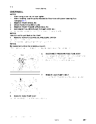
6. DISCONNECT PRESSURE FEED TUBE ASSY
Turn
(a) Using a spanner (24 mm) to hold the pressure port union,
Hold remove the union bolt and the gasket.
(b) Disconnect the pressure feed tube assy.
F41598
7. REMOVE VANE PUMP V BELT
(a) Loosen the 2 bolts and remove the vane pump V belt.
F41599
8. REMOVE VANE PUMP ASSY
(a) Remove the 2 bolts and the vane pump assy.
2005 SIENNA REPAIR MANUAL (RM1163U)
Author : Date : 2897
51-9
POWER STEERING - VANE PUMP ASSY
9. REMOVE POWER STEERING SUCTION PORT UNION
(a) Remove the bolt and the suction port union.
(b) Remove the O-ring from the suction port union.
10. REMOVE FLOW CONTROL VALVE
(a) Remove the pressure port union.
(b) Remove the O-ring from the pressure port union.
(c) Remove the flow control valve and the compression spring.
11. REMOVE VANE PUMP BRACKET REAR
(a) Remove the 2 bolts, nuts, and the vane pump bracket rear from the vane pump assy.
12. REMOVE VANE PUMP HOUSING REAR
(a) Remove the 4 bolts and the vane pump housing rear from the vane pump housing front.
(b) Remove the gasket.
(c) Remove the 2 O-rings from the vane pump housing rear.
13. REMOVE VANE PUMP SIDE PLATE REAR
(a) Remove the wave washer from the vane pump side plate rear.
(b) Remove the vane pump side plate rear.
14. REMOVE VANE PUMP CAM RING
15. REMOVE VANE PUMP SHAFT SNAP RING
(a) Using a screwdriver, remove the vane pump shaft snap
ring from the w/ pulley shaft sub-assy.
C65312
16. REMOVE VANE PUMP ROTOR
(a) Remove the 10 vane pump plates from the vane pump rotor.
(b) Remove the vane pump rotor.
17. REMOVE W/PULLEY SHAFT SUB-ASSY
18. REMOVE PUMP BRACKET FRONT
(a) Remove the bolt and the pump bracket front from the vane pump housing front.
19. REMOVE VANE PUMP HOUSING OIL SEAL
Cloth
(a) Using a screwdriver, remove the vane pump housing oil
seal from the vane pump housing front.
NOTICE:
Be careful not to damage the bushing of the vane pump
housing front.
D30653
2005 SIENNA REPAIR MANUAL (RM1163U)
Author : Date : 2898
51-10
POWER STEERING - VANE PUMP ASSY
20. INSPECT VANE PUMP SHAFT AND BUSH IN
Caliper Gauge HOUSING FRONT
(a) Using a micrometer and a caliper gauge, measure the oil
clearance.
Standard clearance:
0.027 to 0.054 mm (0.00106 to 0.00213 in.)
Maximum clearance: 0.07 mm (0.0028 in.)
If it is more than the maximum, replace the vane pump assy.
Micrometer (b) Check if there is any damege or wear on the bushing of
vane pump housing front and the w/ pulley shaft sub-
assy.
Bushing If necessary, replace the vane pump assy.
W/Pulley Shaft Vane pump
Sub-assy Housing Front D30647
Thickness 21. INSPECT VANE PUMP ROTOR AND VANE PUMP
PLATES
(a) Using a micrometer, measure the thickness of the vane
pump plates.
Minimum thickness:
1.397 to 1.403 mm ( 0.0550 to 0.05524 in.)
D30648
(b) Using a feeler gauge, measure the clearance between
the vane pump rotor groove and the vane pump plate.
Maximum clearance: 0.03 mm (0.0012 in.)
If it is more than the maximum, replace the vane pump assy.
Feeler Gauge
R10282
22. INSPECT FLOW CONTROL VALVE
(a) Coat the flow control valve with power steering fluid and
check that it falls smoothly into the flow control valve hole
by its own weight.
If necessary, replace the vane pump assy.
R11288
2005 SIENNA REPAIR MANUAL (RM1163U)
Author : Date : 2899
51-1 1
POWER STEERING - VANE PUMP ASSY
(b) Check the flow control valve for leakage. Close one of the
Compressed Air
holes and apply compressed air of 392 to 490 kPa (4 to
5 kgf/cm2, 57 to 71 psi) into the opposite side hole, and
confirm that air does not come out from the end holes.
If necessary, replace the vane pump assy.
R07591
23. INSPECT FLOW CONTROL VALVE COMPRESSION
SPRING
(a) Using vernier calipers, measure the free length of the
compression spring.
Minimum free length: 32.24 mm (1.2693 in.)
Vernier Calipers If it is not within the specification, replace the vane pump assy.
R08702
24. INSPECT PRESSURE PORT UNION
If the union seat in the pressure port union is remarkably damaged, it may cause fluid leakage. Replace the
vane pump assy.
25. INSTALL VANE PUMP HOUSING OIL SEAL
Press
(a) Coat a new vane pump housing oil seal lip with power
SST steering fluid.
(b) Using SST and a press, install the vane pump housing oil
seal.
SST 09950-60010 (09951-00330),
09950-70010 (09951-07100)
NOTICE:
W03541 Oil Seal F41624 Make sure that the vane pump housing oil seal is installed
facing in the correct direction.
26. INSTALL PUMP BRACKET FRONT
(a) Install the pump bracket front with the bolt.
Torque: 44 Nm (449 kgfcm, 32 ftlbf)
27. INSTALL W/PULLEY SHAFT SUB-ASSY
Bushing (a) Coat bushing surface of the vane pump housing front with
power steering fluid.
(b) Gradually insert the w/pulley shaft sub-assy from the
pulley side.
NOTICE:
S Do not damage the vane pump housing oil seal lip in
the vane pump housing front.
F40339 S After installation, check the vane pump housing oil
seal lip.
2005 SIENNA REPAIR MANUAL (RM1163U)
Author : Date : 2900
51-12
POWER STEERING - VANE PUMP ASSY
28. INSTALL VANE PUMP CAM RING
Inscribed (a) Align the holes of the vane pump cam ring with 2 straight
Mark pins, and install the vane pump cam ring with inscribed
mark facing upward.
Straight Pin
D30649
29. INSTALL VANE PUMP ROTOR
Inscribed (a) Install the vane pump rotor with inscribed mark facing
Mark downward.
NOTICE:
Make sure that the vane pump rotor is installed facing in the
correct direction.
Inscribed Mark
D30650
30. INSTALL VANE PUMP VANE PLATES
Inward
(a) Coat 10 vane pump plates with power steering fluid.
(b) Install the vane pump plates with the round end facing
outward.
NOTICE:
Make sure that the vane pump plates are installed facing in
Outward the correct direction.
C95777 D30335
31. INSTALL VANE PUMP SHAFT SNAP RING
(a) Using a snap ring expander, install a new vane pump
shaft snap ring onto the w/ pulley shaft sub-assy.
D30651
2005 SIENNA REPAIR MANUAL (RM1163U)
Author : Date : 2901
51-13
POWER STEERING - VANE PUMP ASSY
32. INSTALL VANE PUMP SIDE PLATE REAR
(a) Align the groove of the vane pump cam ring with that of
the vane pump side plate rear, and install the vane pump
side plate rear.
Set
F41480
(b) Install the wave washer so that its protrusions fit into the
slots in the vane pump side plate rear.
(c) Coat 2 new O-rings with power steering fluid and install
them onto the vane pump side plate rear.
R11292
33. INSTALL VANE PUMP HOUSING REAR
Gasket Cutout Part
(a) Install a new gasket onto the vane pump housing front.
NOTICE:
Make sure that the gasket is installed facing in the correct
direction.
(b) Install the vane pump housing rear with the 4 bolts.
Torque: 24 Nm (245 kgfcm, 18 ftlbf)
D30652
34. MEASURE VANE PUMP ROTATION TORQUE
(a) Check that the vane pump rotates smoothly without ab-
normal noise.
(b) Temporarily install the service bolt.
Recommended service bolt:
Thread diameter: 10 mm (0.39 in.)
Thread pitch: 1.25 mm (0.0492 in.)
Bolt length: 50 mm (1.97 in.)
F41492 (c) Using a torque wrench, check the vane pump rotating
torque.
Rotating torque:
0.27 Nm (2.8 kgfcm, 2.4 in.lbf) or less
2005 SIENNA REPAIR MANUAL (RM1163U)
Author : Date : 2902
51-14
POWER STEERING - VANE PUMP ASSY
35. INSTALL VANE PUMP BRACKET REAR
(a) Install the vane pump bracket rear with the 2 bolts and nuts.
Torque: 44 Nm (449 kgfcm, 32 ftlbf)
36. INSTALL FLOW CONTROL VALVE
(a) Coat the compression spring with power steering fluid and install it.
(b) Coat the flow control valve with power steering fluid.
(c) Install the flow control valve.
NOTICE:
Make sure that the flow control valve is installed facing in the correct direction.
(d) Coat a new O-ring with power steering fluid and install it onto the pressure port union.
(e) Install the pressure port union.
Torque: 83 Nm (846 kgfcm, 61 ftlbf)
37. INSTALL POWER STEERING SUCTION PORT UNION
(a) Coat a new O-ring with power steering fluid and install it onto the suction port union.
(b) Install the suction port union with the bolt.
Torque: 13 Nm (133 kgfcm, 10 ftlbf)
38. INSTALL VANE PUMP ASSY
(a) Temporarily install the vane pump assy with the 2 bolts.
A 39. INSTALL VANE PUMP V BELT
(a) Install the vane pump V belt and adjust the V belt tension
(See page ).
B (b) Torque the bolt A.
Torque: 44 Nm (449 kgfcm, 32 ftlbf)
(c) Torque the bolt B.
Torque: 44 Nm (449 kgfcm, 32 ftlbf)
F41599
40. CONNECT PRESSURE FEED TUBE ASSY
Pressure Feed (a) Using a spanner (24 mm) to hold the pressure port union,
Tube Assy connect the pressure feed tube assy with the union bolt
and a new gasket.
Torque: 52 Nm (525 kgfcm, 38 ftlbf)
Stopper NOTICE:
Make sure that the stopper of the pressure feed tube assy
touches the pump bracket front as shown in the illustra-
W03441
F41567 tion, then tighten the union bolt.
41. INSTALL POWER STEERING OIL PRESSURE SWITCH
(a) Install the oil pressure switch to the union bolt.
Torque: 21 Nm (214 kgfcm, 15 ftlbf)
NOTICE:
Make sure that there is no oil on or inside the connector.
(b) Connect the connector.
42. CONNECT OIL RESERVOIR TO PUMP HOSE NO.1
(a) Connect the oil reservoir to pump hose No.1.
(b) Install the clip.
2005 SIENNA REPAIR MANUAL (RM1163U)
Author : Date : 2903
51-15
POWER STEERING - VANE PUMP ASSY
43. INSTALL FRONT FENDER APRON SEAL RH
44. INSTALL FRONT WHEEL RH
Torque: 103 Nm (1,050 kgfcm, 76 ftlbf)
45. BLEED POWER STEERING FLUID (See page 51-3 )
46. INSPECT FLUID LEAK
2005 SIENNA REPAIR MANUAL (RM1163U)
Author : Date : 2904
◦ Jabse Service Manual Search 2026 ◦ Jabse Pravopis ◦ onTap.bg ◦ Other service manual resources online : Fixya ◦ eServiceinfo