Service Manuals, User Guides, Schematic Diagrams or docs for : . Car Manuals Toyota Sienna 2004-2007 Approved SRM 20 20419l02 w040001
<< Back | HomeMost service manuals and schematics are PDF files, so You will need Adobre Acrobat Reader to view : Acrobat Download Some of the files are DjVu format. Readers and resources available here : DjVu Resources
For the compressed files, most common are zip and rar. Please, extract files with Your favorite compression software ( WinZip, WinRAR ... ) before viewing. If a document has multiple parts, You should download all, before extracting.
Good luck. Repair on Your own risk. Make sure You know what You are doing.
Image preview - the first page of the document
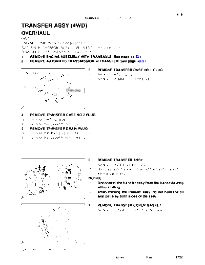
>> Download w040001 documenatation <<
Text preview - extract from the document
31-9
TRANSFER - TRANSFER ASSY (4WD)
TRANSFER ASSY (4WD)
3104E-02
OVERHAUL
HINT:
ENGINE COMPONENTS: See page 14-17
AUTOMATIC TRANSMISSION COMPONENTS: See page 40-8
TRANSFER COMPONENTS: See page 31-3
1. REMOVE ENGINE ASSEMBLY WITH TRANSAXLE (See page 14-33 )
2. REMOVE AUTOMATIC TRANSMISSION W/TRANSFER (See page 40-9 )
3. REMOVE TRANSFER CASE NO.1 PLUG
No.2 plug (a) Remove the No.1 plug.
(b) Remove the gasket from the plug.
No.1 plug
Drain plug
C82977
4. REMOVE TRANSFER CASE NO.2 PLUG
(a) Remove the No.2 plug.
(b) Remove the gasket from the plug.
5. REMOVE TRANSFER DRAIN PLUG
(a) Remove the drain plug and drain the oil.
(b) Remove the gasket from the drain plug.
6. REMOVE TRANSFER ASSY
(a) Remove the 2 bolts and 6 nuts.
(b) Using a plastic hammer, drive out the transfer assy from
the transaxle assy.
NOTICE:
S Disconnect the transfer assy from the transaxle assy
without tilting.
S When moving the transfer assy, do not hold the oil
C82785 seal parts by both sides of the assy.
7. REMOVE TRANSFER COVER GASKET
(a) Remove the gasket from the transfer assy.
C82798
2005 SIENNA REPAIR MANUAL (RM1163U)
Author : Date : 2722
31-10
TRANSFER - TRANSFER ASSY (4WD)
8. REMOVE TRANSFER CASE BREATHER PLUG
(a) Using a screwdriver and a hammer, remove the breather
plug from the case cover.
C94714
9. REMOVE TRANSFER CASE COVER NO.1
(a) Remove the 8 bolts.
C83507
(b) Using a brass bar and a hammer, remove the case cover
from the case.
NOTICE:
Be careful not to damage the mating surfaces of the case
and cover.
C50303
10. REMOVE BREATHER OIL DEFLECTOR
(a) Remove the bolt and breather oil deflector from the case
cover.
C67665
11. REMOVE TRANSFER DYNAMIC DAMPER
(a) Remove the 3 bolts and the dynamic damper from the ex-
tension housing.
C82802 D30654
2005 SIENNA REPAIR MANUAL (RM1163U)
Author : Date : 2723
31-1 1
TRANSFER - TRANSFER ASSY (4WD)
12. REMOVE TRANSFER CASE STRAIGHT PIN
(a) Remove the 4 transfer case straight pins from the transfer case.
13. REMOVE TRANSFER & TRANSAXLE SETTING STUD BOLT
(a) Remove the 4 stud bolts.
14. FIX TRANSFER ASSY
(a) Fix the transfer assy to the overhaul attachment.
15. REMOVE TRANSFER EXTENSION HOUSING DUST
DEFLECTOR
(a) Using a plastic hammer, remove the dust deflector from
the extension housing.
C82788
16. REMOVE TRANSFER EXTENSION HOUSING TYPE T
OIL SEAL
(a) Using SST, remove the oil seal from the extension hous-
ing.
SST 09308-00010
NOTICE:
Be careful not to damage the oil-seal-fitted surface of the
SST housing and the inside surface of the bush.
C82978
17. REMOVE TRANSFER EXTENSION HOUSING
SUB-ASSY
(a) Remove the 4 bolts.
C82790
(b) Using a plastic hammer, remove the extension housing
from the case.
C82791
2005 SIENNA REPAIR MANUAL (RM1163U)
Author : Date : 2724
31-12
TRANSFER - TRANSFER ASSY (4WD)
18. INSPECT PRELOAD
(a) Using SST and a torque wrench, check the initial torque
SST within the backlash range.
SST 09326-2001 1
Torque: 0.9 - 1.4 Nm (9 - 14 kgfcm, 8.0 - 12.4 in.lbf)
HINT:
Use a torque wrench with a fulcrum length of 160 mm (6.30 in.)
(b) Using SST and a torque wrench, check the initial torque
C82792 C83635 with the driven pinion being contact with the ring gear
face.
SST 09326-2001 1
Torque: Driven pinion preload
+0.15 - 0.30 Nm (+1.6 - 3.1 kgfcm, +1.3 - 2.7 in.lbf)
HINT:
Use a torque wrench with a fulcrum length of 160 mm (6.30 in.)
19. INSPECT BACKLASH
(a) Set the dial gauge perpendicular to the tooth face of the
ring gear, fix the driven pinion and check the backlash
while moving the gear.
Backlash: 0.10 - 0.15 mm (0.0039 - 0.0059 in.)
NOTICE:
Check it at 3 points or more on the gear periphery.
C50309
20. INSPECT TOOTH CONTACT BETWEEN RING GEAR
AND DRIVEN PINION
(a) Apply red lead primer thinly and uniformly to both faces
of the ring gear and rotate it several times.
NOTICE:
Check the tooth contact on the ring gear at 4 places or
more.
C50346
2005 SIENNA REPAIR MANUAL (RM1163U)
Author : Date : 2725
31-13
TRANSFER - TRANSFER ASSY (4WD)
(b) Proper washer location is shown in the illustration.
Heel Contact Face Contact
Select an adjusting washer that will bring
the driven pinion closer to the ring gear.
Toe Contact Flank Contact
Proper Contact
Select an adjusting washer that will shift
C30886
K3673
the drive pinion away from the ring gear.
C83636
21. REMOVE CTR DIFFERENTIAL LOCK SLEEVE
(a) Using a snap ring pliers, remove the shaft snap ring.
C50310 C83637
(b) Using SST, remove the center differential lock sleeve.
SST 09308-00010
SST
C51144 C83638
22. REMOVE O-RING
(a) Using a screwdriver with the tip protected by taping, re-
move the O-ring from the center differential lock sleeve.
NOTICE:
Be careful not to damage the lock sleeve's groove for the
O-ring.
C50311
2005 SIENNA REPAIR MANUAL (RM1163U)
Author : Date : 2726
31-14
TRANSFER - TRANSFER ASSY (4WD)
23. REMOVE TRANSFER CASE OIL SEAL
(a) Using SST, remove the oil seal from the case.
SST 09308-00010
NOTICE:
Be careful not to damage the oil-seal-fitted surface of the
case.
SST
C50328 C83630
24. REMOVE TRANSFER RH BEARING RETAINER OIL
SEAL
(a) Using SST, remove the oil seal from the right bearing re-
tainer.
SST 09308-00010
NOTICE:
Be careful not to damage the oil-seal-fitted surface of the
SST retainer.
C82980
25. REMOVE TRANSFER RH BEARING RETAINER
SUB-ASSY
(a) Remove the 7 bolts from the right bearing retainer.
C83509
(b) Using a screwdriver and a hammer, make a clearance be-
tween the right bearing retainer and the transfer case.
C82797
(c) Using SST, remove the right bearing retainer from the
transfer case.
SST SST 09520-10021
C82981
2005 SIENNA REPAIR MANUAL (RM1163U)
Author : Date : 2727
31-15
TRANSFER - TRANSFER ASSY (4WD)
26. REMOVE TRANSFER RH BEARING RETAINER
O-RING
(a) Using a screwdriver with the tip protected by taping, re-
move the 2 O-rings from the right bearing retainer.
NOTICE:
Be careful not to damage the retainer's groove for the O-
ring.
C50313
27. REMOVE CENTER DIFFERENTIAL CASE TAPERED
ROLLER BEARING
SST
(a) Hold the right bearing retainer in a vise.
(b) Using SST, remove the outer race, washer and oil seal
from the right bearing retainer.
SST 09308-00010
NOTICE:
Be careful not to damage the oil-seal-fitted surface of the
C50315 C83639 retainer.
28. REMOVE SIDE GEAR SHAFT HOLDER BEARING
(a) Using a snap ring pliers, remove the side gear shaft hold-
er hole snap ring.
(b) Remove the side gear shaft holder bearing from the right
bearing retainer.
C50316 C83640
29. REMOVE TRANSFER RING GEAR MOUNTING CASE
(a) Remove the ring gear mounting case assy from the case.
C67673
2005 SIENNA REPAIR MANUAL (RM1163U)
Author : Date : 2728
31-16
TRANSFER - TRANSFER ASSY (4WD)
30. REMOVE CENTER DIFFERENTIAL CASE TAPERED
ROLLER BEARING
SST (a) RH side:
Using SST, remove the inner race of the center differential
case tapered roller bearing from the ring gear mounting
case assy.
SST 09950- 40011 (09951- 04010, 09952- 04010,
09953- 04020, 09954- 04010, 09955- 04061,
C67674 C83641 09957- 04010, 09958- 04011), 09950- 60010
(09951-00420)
NOTICE:
Apply grease to the screw thread and the tip of the SST be-
fore use.
HINT:
When the roller comes off due to deformation of the gauge,
completely remove the roller and take away remaining inner
SST
races of the center differential case tapered roller bearing from
the ring gear mounting case assy.
SST 09950- 00020, 09950- 00030, 09950- 60010
(09951-00430)
NOTICE:
C67685 C83642 Apply grease to the screw thread and the tip of the SST be-
fore use.
(b) LH side:
Using SST, remove the inner race of the center differential
case tapered roller bearing from the ring gear mounting
SST case assy.
SST 09950- 40011 (09951- 04010, 09952- 04010,
09953- 04020, 09954- 04010, 09955- 04061,
09957- 04010, 09958- 04011), 09950- 60010
(09951-00360)
C68270 C83643 NOTICE:
Apply grease to the screw thread and the tip of the SST be-
fore use.
HINT:
When the roller comes off due to deformation of the gauge,
completely remove the roller and take away remaining inner
races of the center differential case tapered roller bearing from
SST
the ring gear mounting case assy.
SST 09950- 00020, 09950- 00030, 09950- 60010
(09951-00360)
NOTICE:
C50320 C83644 Apply grease to the screw thread and the tip of the SST be-
fore use.
2005 SIENNA REPAIR MANUAL (RM1163U)
Author : Date : 2729
31-17
TRANSFER - TRANSFER ASSY (4WD)
31. REMOVE RING GEAR
(a) Put matchmarks on the ring gear mounting case assy and
the ring gear.
(b) Remove the 12 bolts.
Matchmarks
C67676 C83645
(c) Using a plastic hammer, remove the ring gear by tapping
around its periphery.
NOTICE:
Do not damage the tooth face of the ring gear.
C67677
32. INSPECT RUNOUT OF TRANSFER RING GEAR
MOUNTING CASE
(a) Using a dial indicator, check for the ring gear mounting
case runout.
Maximum runout: 0.03 mm (0.0012 in.)
C99000
33. REMOVE DRIVEN PINION
(a) Using SST and a hammer, unstake the staked part of the
gear nut.
SST 09930-00010
C82795
(b) Using SST, remove the gear nut.
SST 09326-2001 1, 09556-16030
SST
SST
C82984
2005 SIENNA REPAIR MANUAL (RM1163U)
Author : Date : 2730
31-18
TRANSFER - TRANSFER ASSY (4WD)
(c) Using a press, remove the driven pinion, bearing inner
rear race and bearing spacer.
NOTICE:
S Put a shop rug to prevent the driven pinion from drop-
ping.
S Place something like wood blocks under the case to
keep it level.
C82796
34. REMOVE TRANSFER DRIVEN PINION FRONT
BEARING
SST (a) Using SST and a press, remove the inner race from the
driven pinion.
SST 09950-00020
C50327 C83646
35. REMOVE CENTER DIFFERENTIAL CASE TAPERED
ROLLER BEARING
(a) Using a brass bar and a hammer, lightly strike the outer
race at 2 points to remove it from the case.
36. REMOVE RING GEAR MOUNTING CASE PLATE
WASHER
C50329
37. REMOVE TRANSFER DRIVEN PINION FRONT
BEARING
(a) Using a brass bar and a hammer, lightly strike the outer
race at 2 points to remove it from the case.
38. REMOVE TRANSFER OUTPUT WASHER
C82781
39. REMOVE TRANSFER DRIVEN PINION REAR
BEARING
(a) Using a brass bar and a hammer, lightly strike the outer
race at 2 points to remove it from the case.
C50331
2005 SIENNA REPAIR MANUAL (RM1163U)
Author : Date : 2731
31-19
TRANSFER - TRANSFER ASSY (4WD)
40. INSTALL TRANSFER DRIVEN PINION REAR
BEARING
SST
(a) Using SST and a press, install the outer race to the case.
SST 09950- 60010 (09951- 00620), 09950- 70010
(09951-07150)
NOTICE:
Place something like wood blocks under the case to keep
it level.
C82982
41. INSTALL TRANSFER OUTPUT WASHER
(a) Install the washer to the case.
HINT:
Reuse the washer used before disassembly.
42. INSTALL TRANSFER DRIVEN PINION FRONT
SST BEARING
(a) Install the outer race to the case with SST, a bolt and a nut.
SST 09950- 60010 (09951- 00750, 09951- 00770,
09951-00810), 09316-60011 (09316-00061)
C50335 C83647
43. INSTALL RING GEAR MOUNTING CASE PLATE WASHER
(a) Install the washer to the case.
HINT:
Reuse the washer used before disassembly.
44. INSTALL CENTER DIFFERENTIAL CASE TAPERED
ROLLER BEARING
SST
(a) Using SST and a press, install the outer race to the case.
SST 09950- 70010 (09951- 07200), 09316- 60011
(09316-00021)
C50336 C83648
45. INSTALL TRANSFER DRIVEN PINION FRONT
BEARING
SST
(a) Using SST and a press, install the inner race to the driven
pinion.
SST 09316-6001 1 (09316-00041)
C50337 C83649
2005 SIENNA REPAIR MANUAL (RM1163U)
Author : Date : 2732
31-20
TRANSFER - TRANSFER ASSY (4WD)
46. INSTALL DRIVEN PINION
(a) Install the driven pinion to the case.
C50338
(b) Install a new bearing spacer and a new bearing rear to the
driven pinion.
C50339
(c) Using SST, tighten a new gear nut with a standard torque.
SST 09326-2001 1, 09556-16030
Torque: 277 - 378 Nm (2,820 - 3,853 kgfcm, 204 - 279
ftlbf)
NOTICE:
Do not stake the gear nut.
SST HINT:
Use a torque wrench with a fulcrum length of 750 mm (29.53 in.)
C82983
47. INSPECT AND ADJUST DRIVEN PINION PRELOAD
(a) Using SST and a torque wrench, measure the initial
SST torque of the driven pinion.
SST 09326-2001 1
Preload (at starting):
New bearing:
1.1 - 1.6 Nm (11 - 16 kgfcm, 9.7 - 14.2 in.lbf)
Used bearing:
C82792 C83635 0.9 - 1.4 Nm (9 - 14 kgfcm, 8.0 - 12.4 in.lbf)
HINT:
Use a torque wrench with a fulcrum length of 160 mm (6.30 in.)
NOTICE:
Measure it after rotating the bearing in both clockwise and
counter clockwise directions to make it fit.
(b) If the preload is too large, replace the bearing spacer with
new one.
(c) If the preload is too small, repeatedly adjust the preload
by tightening the lock nut 5 - 10 degrees at a time until the
standard value is obtained.
2005 SIENNA REPAIR MANUAL (RM1163U)
Author : Date : 2733
31-21
TRANSFER - TRANSFER ASSY (4WD)
(d) If the preload is insufficient even though the tightening
torque of the lock nut exceeds the maximum of the stan-
dard value, loosen the lock nut and apply gear oil SAE 90
(GL-5) to the lock nut and the screw thread and the base
of the driven pinion. And then repeat the preceding opera-
tion. If the tightening torque is smaller than the standard,
replace the bearing spacer with new one and adjust it.
SST 09326-2001 1, 09556-16030
Torque: 378 Nm (3,855 kgfcm, 279 ftlbf)
48. INSTALL RING GEAR
Boiling water (a) Heat the ring gear in boiling water to 90 - 100 _C (194 -
212 _F).
(b) Completely remove grease and moisture on the mating
surfaces of the ring gear and the ring gear mounting case.
ZK8214 C83651
(c) Align the matchmarks on the ring gear and ring gear
mounting case and quickly assemble them.
(d) Tighten the12 bolts.
Matchmarks
Torque: 78 Nm (790 kgfcm, 57 ftlbf)
NOTICE:
S Tighten the bolts in diagonal order in splitting several
times.
S After the ring gear has well cooled down, tighten the
C50361 C83652 bolts.
S Make paint marks, etc, do the procedure while check-
ing the bolts retightened.
49. INSTALL CENTER DIFFERENTIAL CASE TAPERED
ROLLER BEARING
(a) RH side:
Using SST and a press, install the inner race of the center
differential case tapered roller bearing to the ring gear
SST mounting case assy.
SST 09506-35010, 09950-60010 (09951-00430)
NOTICE:
C50342 C83653 When replacing the inner race, replace the outer race, too.
2005 SIENNA REPAIR MANUAL (RM1163U)
Author : Date : 2734
31-22
TRANSFER - TRANSFER ASSY (4WD)
(b) LH side:
Using SST and a press, install the inner race of the center
differential case tapered roller bearing to the ring gear
mounting case assy.
SST 09223-00010
SST
NOTICE:
When replacing the inner race, replace the outer race, too.
C67688
50. INSTALL TRANSFER RING GEAR MOUNTING CASE
(a) Install the ring gear mounting case assy to the case.
NOTICE:
Damage to the spline, bearing's rotating surface and gear
face may cause decrease in their strength. Care should be
taken at the time of installation.
51. INSTALL TRANSFER RING GEAR MOUNTING CASE
WASHER NO.2
C67673 HINT:
Reuse the washer used before disassembly.
52. INSTALL CENTER DIFFERENTIAL CASE TAPERED
SST ROLLER BEARING
(a) Using SST and a press, install the outer race to the right
bearing retainer.
SST 09950- 60010 (09951- 00620), 09950- 70010
(09951-07150)
C50344 C83654
53. INSTALL TRANSFER RH BEARING RETAINER
SUB-ASSY
(a) Place the transfer with the face where the right bearing re-
tainer is to be installed facing up.
(b) Center-align the ring gear mounting case assy and the
case.
C57486
(c) Insert the SST into the right bearing retainer.
SST 09387-00090
NOTICE:
Insert SST straight in order not to damage the oil seal lip.
SST
C57487
2005 SIENNA REPAIR MANUAL (RM1163U)
Author : Date : 2735
31-23
TRANSFER - TRANSFER ASSY (4WD)
(d) Insert the right bearing retainer together with the SST into
the case.
NOTICE:
Hard interference between the case and the retainer, and
between the center differential control coupling assy and
SST should be carefully avoided.
HINT:
If the retainer cannot be inserted, tap it in with a plastic hammer.
C57488
(e) After inserting the right bearing retainer into the case, re-
move the SST.
SST
C57489
(f) Tighten the 7 bolts.
Torque: 28 Nm (286 kgfcm, 21 ftlbf)
C83509
2005 SIENNA REPAIR MANUAL (RM1163U)
Author : Date : 2736
31-24
TRANSFER - TRANSFER ASSY (4WD)
54. INSPECT BACKLASH
(a) Set the dial gauge perpendicular to the ring gear face, fix
the driven pinion, and check the backlash by moving the
ring gear.
Backlash: 0.10 - 0.15 mm (0.0039 - 0.0059 in.)
NOTICE:
Measure it at 3 points or more on the ring gear periphery.
(b) If the measured value is out of the standard, select a prop-
C50309 er washer for the center differential case tapered roller
bearing on the LH side from the table below and install it
to obtain the standard value.
Mark Washer Thickness mm (in.) Mark Washer Thickness mm (in.) Mark Washer Thickness mm (in.)
AA 2.07 (0.0814) AB 2.10 (0.0826) AC 2.13 (0.0838)
BA 2.16 (0.0850) BB 2.19 (0.0862) BC 2.22 (0.0874)
CA 2.25 (0.0885) CB 2.28 (0.0897) CC 2.31 (0.0909)
DA 2.34 (0.0921) DB 2.37 (0.0933) DC 2.40 (0.0944)
EA 2.43 (0.0956) EB 2.46 (0.0968) EC 2.49 (0.0980)
FA 2.52 (0.0992) FB 2.55 (0.1003) FC 2.58 (0.1015)
GA 2.61 (0.1027) GB 2.64 (0.1039) GC 2.67 (0.1051)
HA 2.70 (0.1062) HB 2.73 (0.1074) HC 2.76 (0.1086)
JA 2.79 (0.1098) JB 2.82 (0.1110) JC 2.85 (0.1122)
KA 2.88 (0.1133) KB 2.91 (0.1145) KC 2.94 (0.1157)
LA 2.97 (0.1169) LB 3.00 (0.1181)
HINT:
When the backlash is larger or smaller than the standard, select
a thinner or thicker washer respectively.
(c) Proper washer location is shown in the illustration.
Ring gear mounting
case washer
C50345 C83655
55. INSPECT TOOTH CONTACT BETWEEN RING GEAR
AND DRIVEN PINION
(a) Apply red lead primer thinly and uniformly to both faces
of the ring gear and rotate it several times.
NOTICE:
Check the tooth contact on the ring gear at 4 places or
more.
C50346
2005 SIENNA REPAIR MANUAL (RM1163U)
Author : Date : 2737
31-25
TRANSFER - TRANSFER ASSY (4WD)
(b) Observe the pattern shown by red lead primer.
Heel Contact Face Contact
Select an adjusting washer that will bring
the driven pinion closer to the ring gear.
Toe Contact Flank Contact
Proper Contact
Select an adjusting washer that will shift
C30886
K3673
the drive pinion away from the ring gear.
C83636
(c) In the case of faulty tooth contact, select a washer for the
driven pinion bearing front side from the following table
and reinstall it.
NOTICE:
If the washer thickness is changed, the backlash will be
also changed.
Mark Washer Thickness mm (in.) Mark Washer Thickness mm (in.) Mark Washer Thickness mm (in.)
AA 1.20 (0.0472) AC 1.22 (0.0480) BB 1.24 (0.0488)
CA 1.26 (0.0496) CC 1.28 (0.0503) DB 1.30 (0.0511)
EA 1.32 (0.0519) EC 1.34 (0.0527) FB 1.36 (0.0535)
GA 1.38 (0.0543) GC 1.40 (0.0551) HB 1.42 (0.0559)
JA 1.44 (0.0566) JC 1.46 (0.0574) KB 1.48 (0.0582)
LA 1.50 (0.0590) LC 1.52 (0.0598) MB 1.54 (0.0606)
NA 1.56 (0.0614) NC 1.58 (0.0622) PB 1.60 (0.0629)
QA 1.62 (0.0637) QC 1.64 (0.0645)
(d) The location of the washer for tooth contact adjustment
is shown in the illustration.
Output shaft washer
C50363 C83656
2005 SIENNA REPAIR MANUAL (RM1163U)
Author : Date : 2738
31-26
TRANSFER - TRANSFER ASSY (4WD)
56. ADJUST TOTAL PRELOAD
(a) Using SST and a torque wrench, measure the initial
SST torque with the driven pinion being contact with the ring
gear face.
SST 09326-2001 1
Torque:
New bearing:
Driven pinion preload +0.2 - 0.4 Nm (+2.3 - 3.9
C82792 C83635 kgfcm, +1.8 - 3.5 in.lbf)
Used bearing:
Driven pinion preload +0.15 - 0.30 Nm (+1.6 - 3.1
kgfcm, +1.3 - 2.7 in.lbf)
NOTICE:
Before measurement, rotate the bearing in both directions
several times to make it fit.
HINT:
Use a torque wrench with a fulcrum length of 160 mm (6.30 in.)
(b) If the value is out of the standard range, select the washer
for the center differential case tapered roller bearing RH
side from the following table and reinstall it.
Mark Washer Thickness mm (in.) Mark Washer Thickness mm (in.) Mark Washer Thickness mm (in.)
AA 1.47 (0.0578) AB 1.50 (0.0590) AC 1.53 (0.0602)
BA 1.56 (0.0614) BB 1.59 (0.0625) BC 1.62 (0.0637)
CA 1.65 (0.0649) CB 1.68 (0.0661) CC 1.71 (0.0673)
DA 1.74 (0.0685) DB 1.77 (0.0696) DC 1.80 (0.0708)
EA 1.83 (0.0720) EB 1.86 (0.0732) EC 1.89 (0.0744)
FA 1.92 (0.0755) FB 1.95 (0.0767) FC 1.98 (0.0779)
GA 2.01 (0.0790) GB 2.04 (0.0803) GC 2.07 (0.0814)
HA 2.10 (0.0826) HB 2.13 (0.0838) HC 2.16 (0.0850)
JA 2.19 (0.0862) JB 2.22 (0.0874) JC 2.25 (0.0885)
KA 2.28 (0.0897) KB 2.31 (0.0909) KC 2.34 (0.0921)
LA 2.37 (0.0933) LB 2.40 (0.0944) LC 2.43 (0.0956)
MA 2.46 (0.0968) MB 2.49 (0.0980) MC 2.52 (0.0992)
NA 2.55 (0.1003) NB 2.58 (0.1015)
(c) The location of the washer for preload adjustment is
Ring gear mounting shown in the illustration.
case washer No. 2
C50349 C83657
2005 SIENNA REPAIR MANUAL (RM1163U)
Author : Date : 2739
31-27
TRANSFER - TRANSFER ASSY (4WD)
(d) Using a chisel, stake the gear nut.
C70532
57. REMOVE TRANSFER RH BEARING RETAINER
SUB-ASSY
(a) Remove the 7 bolts from the right bearing retainer.
C83509
(b) Using a screwdriver and a hammer, make a clearance be-
tween the right bearing retainer and the transfer case.
C82797
(c) Using SST, remove the right bearing retainer from the
transfer case.
SST SST 09520-10021
C82981
58. REMOVE CENTER DIFFERENTIAL CASE TAPERED
ROLLER BEARING
SST
(a) Hold the right bearing retainer in a vise.
(b) Using SST, remove the outer race and washer from the
right bearing retainer.
SST 09308-00010
C50341 C83688
2005 SIENNA REPAIR MANUAL (RM1163U)
Author : Date : 2740
31-28
TRANSFER - TRANSFER ASSY (4WD)
59. INSTALL SIDE GEAR SHAFT HOLDER BEARING
(a) Install the side gear shaft holder bearing to the right bear-
ing retainer.
(b) Using a snap ring pliers, install the side gear shaft holder
hole snap ring.
HINT:
Check that the snap ring is fit in the groove of the retainer.
C50364 C83699
60. INSTALL TRANSFER RH BEARING RETAINER OIL
SEAL
1.5 - 2.5 mm SST (a) Using SST and a press, install the oil seal to the right bear-
(0.059 - 0.098 in.)
ing retainer.
NOTICE:
Carefully press-fit so that the oil seal will not be tilted.
(b) Apply small amount of MP grease No. 2 to the oil seal lip.
SST 09950- 60010 (09951- 00360, 09951- 00540,
C50350 C83689 09952-06010), 09950-70010 (09951-07150)
61. INSTALL TRANSFER RING GEAR MOUNTING CASE WASHER NO.2
(a) Install the selected ring gear mounting washer to the right bearing retainer.
62. INSTALL CENTER DIFFERENTIAL CASE TAPERED
ROLLER BEARING
SST
(a) Using SST and a press, install the outer race to the right
bearing retainer.
SST 09950- 60010 (09951- 00620), 09950- 70010
(09951-07150)
C51147 C83690
63. INSTALL O-RING
(a) Apply hypoid gear oil to a new O-ring.
(b) Install the 2 O-rings to the right bearing retainer.
NOTICE:
Be careful not to twist the O-ring and fit it into the retainer's
groove properly.
C50352
2005 SIENNA REPAIR MANUAL (RM1163U)
Author : Date : 2741
31-29
TRANSFER - TRANSFER ASSY (4WD)
64. INSTALL TRANSFER RH BEARING RETAINER
SUB-ASSY
(a) Place the transfer with the face where the right bearing re-
tainer is to be installed facing up.
(b) Center-align the center differential control coupling assy
and the case.
C57486
(c) Insert SST into the right bearing retainer.
SST 09387-00090
NOTICE:
Insert SST straight in order not to damage the oil seal.
SST
C57487
(d) Insert the right bearing retainer together with SST into the
case.
NOTICE:
S Prevent hard interference between the case and the
retainer, and between the SST and the center differen-
tial control coupling assy.
S Carefully check for damage and incorrect fitting of the
retainer's O-ring.
C57488 HINT:
If the retainer cannot be inserted into the case, tap it in with a
plastic hammer.
(e) After inserting the right bearing retainer into the case, re-
move the SST.
SST
C57489
2005 SIENNA REPAIR MANUAL (RM1163U)
Author : Date : 2742
31-30
TRANSFER - TRANSFER ASSY (4WD)
(f) Tighten the 7 bolts.
Torque: 28 Nm (286 kgfcm, 21 ftlbf)
C83509
65. INSPECT TOTAL PRELOAD
(a) Using SST and a torque wrench, measure the initial
SST torque with the driven pinion being contact with the ring
gear face.
SST 09326-2001 1
Torque:
New bearing:
Driven pinion preload +0.2 - 0.4 Nm
C82792 C83650 (+2.3 - 3.9 kgfcm, +1.8 - 3.5 in.lbf)
Used bearing:
Driven pinion preload +0.15 - 0.30 Nm
(+1.6 - 3.1 kgfcm, +1.3 - 2.7 in.lbf)
HINT:
Use a torque wrench with a fulcrum length of 160 mm (6.30 in.)
0.7 - 1.3 mm 66. INSTALL TRANSFER RH BEARING RETAINER OIL
(0.028 - 0.051 in.) SEAL
(a) Using SST, drive the oil seal into the right bearing retainer
to the position shown in the illustration.
SST 09223-4601 1
NOTICE:
Drive it in carefully so that it will not be tilted.
(b) Apply MP grease to the oil seal lip.
SST
C50351 C83691
67. INSTALL TRANSFER CASE OIL SEAL
(a) Using SST, drive the case oil seal into the case to the posi-
tion shown in the illustration.
SST 09387-00010, 09950-70010 (09951-07150)
NOTICE:
Drive it in carefully so that it will not be tilted.
SST 8.7 - 9.3 mm (b) Apply small amount of MP grease to the oil seal lip.
(0.343 - 0.366 in.)
C50353 C83631
2005 SIENNA REPAIR MANUAL (RM1163U)
Author : Date : 2743
31-31
TRANSFER - TRANSFER ASSY (4WD)
68. INSTALL CTR DIFFERENTIAL LOCK SLEEVE
(a) Apply hypoid gear oil to a new O-ring.
(b) Install the O-ring to the center differential lock sleeve.
NOTICE:
Be careful not to twist the O-ring and fit it into the retainer's
groove properly.
C50354
(c) Using SST, install the center differential lock sleeve to the
case.
SST 09950- 60010 (09951- 00610), 09950- 70010
(09951-07150)
SST
C51160 C83692
(d) Using a snap ring pliers, install the shaft snap ring.
NOTICE:
Check that the snap ring is fitted in the groove of the center
differential control coupling assy.
C50365 C83693
69. INSTALL TRANSFER EXTENSION HOUSING TYPE T
OIL SEAL
(a) Using SST, drive the oil seal into the extension housing
1.1 - 1.9 mm
to the position shown in the illustration.
(0.043 - 0.075 in.) SST 09950- 60010 (09951- 00380, 09951- 00580,
SST 09952-06010), 09950-70010 (09951-07150)
NOTICE:
Drive it in carefully so that it ◦ Jabse Service Manual Search 2026 ◦ Jabse Pravopis ◦ onTap.bg ◦ Other service manual resources online : Fixya ◦ eServiceinfo