Service Manuals, User Guides, Schematic Diagrams or docs for : . Car Manuals Toyota Sienna 2004-2007 Approved SRM 44 systemci 051sls
<< Back | HomeMost service manuals and schematics are PDF files, so You will need Adobre Acrobat Reader to view : Acrobat Download Some of the files are DjVu format. Readers and resources available here : DjVu Resources
For the compressed files, most common are zip and rar. Please, extract files with Your favorite compression software ( WinZip, WinRAR ... ) before viewing. If a document has multiple parts, You should download all, before extracting.
Good luck. Repair on Your own risk. Make sure You know what You are doing.
Image preview - the first page of the document
>> Download 051sls documenatation <<
Text preview - extract from the document
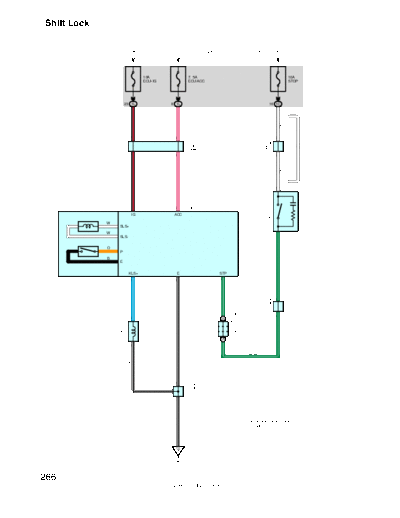
Shift Lock
From Power Source System (See Page 58)
10A 7. 5A 10A
ECU- IG ECU ACC STOP
23 1L 8 1L 16 1C
B- R
P
(*1)
W
Connector
87 88 C
Junction
J18
(* 2)
W
Junction
J15
Connector
77 78 C
(*1)
W
B- R
P
2
S8
1 6 Shift Lock Control ECU
Stop Light SW
IG ACC
W
SLS+
S12
W
SLS- 1
O
P
B
E
G- W
KLS+ E STP
12 8 7
G- W
L- W
Connector
A
Junction
Junction Connector
J2
A
J 3(A), J 4(B)
4 6 B
Key Interlock
W- B
Solenoid
K4
23 A
3
G- W
W- B
Connector
72
Junction
71
J18
1
W- B
* 1 : w/ Dynamic Laser Cruise Control
* 2 : Except *1
IE
266
2005 SIENNA (EWD613U)
System Outline
1. Shift Lock Mechanism
When the brake pedal is depressed with the ignition SW is turned on (Stop light SW on), the shift lock control ECU is
activated and allows the driver to change the shift lever to a position other than P position.
2. Key Interlock Mechanism
When the ignition SW is turned on and the shift lever is at a position other than P position, shift lock control ECU is activated
to flow current to the key interlock solenoid. This inhibits to turn the ignition SW from on to OFF position.
Service Hints
S8 Shift Lock Control ECU
6-Ground : Approx. 12 volts with the ignition SW at ACC or ON position
1-Ground : Approx. 12 volts with the ignition SW at ON position
7-Ground : Approx. 12 volts with the brake pedal depressed
8-Ground : Always continuity
: Parts Location
Code See Page Code See Page Code See Page
J2 33 J15 36 S8 37
J3 A 36 J18 36 S12 37
J4 B 36 K4 36
: Junction Block and Wire Harness Connector
Code See Page Junction Block and Wire Harness (Connector Location)
1C 27 Engine Room Main Wire and Driver Side J/B (Lower Finish Panel)
1L 27 Instrument Panel Wire and Driver Side J/B (Lower Finish Panel)
: Ground Points
Code See Page Ground Points Location
IE 46 Left Kick Panel
267
2005 SIENNA (EWD613U)
◦ Jabse Service Manual Search 2026 ◦ Jabse Pravopis ◦ onTap.bg ◦ Other service manual resources online : Fixya ◦ eServiceinfo