Service Manuals, User Guides, Schematic Diagrams or docs for : . Car Manuals Toyota Sienna 2004-2007 Approved SRM 46 introduc howtouse
<< Back | HomeMost service manuals and schematics are PDF files, so You will need Adobre Acrobat Reader to view : Acrobat Download Some of the files are DjVu format. Readers and resources available here : DjVu Resources
For the compressed files, most common are zip and rar. Please, extract files with Your favorite compression software ( WinZip, WinRAR ... ) before viewing. If a document has multiple parts, You should download all, before extracting.
Good luck. Repair on Your own risk. Make sure You know what You are doing.
Image preview - the first page of the document
>> Download howtouse documenatation <<
Text preview - extract from the document
                                                                   INTRODUCTION                                         IN-5


HOW TO USE THIS MANUAL
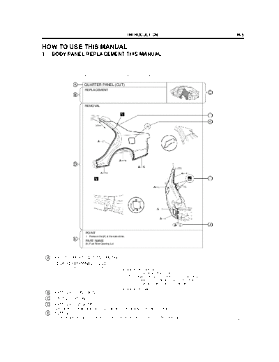
1.    BODY PANEL REPLACEMENT THIS MANUAL


                           BP-34                                   BODY PANEL REPLACEMENT


                           QUARTER PANEL (CUT)
                           REPLACEMENT


                           REMOVAL


                            POINT
                            1   Remove the [A] at the same time.
                            PART NAME
                            [A] Fuel Filler Opening Lid


     A : REPLACEMENT PART AND METHOD
        QUARTER PANEL (CUT)
                                                             Replacement method
                                                             (ASSY) ... Assembly replacement
                                                             (CUT) ... Major cutting (less than 1 / 2 of part used)
                                                             (CUT-H) ... Half cutting (about 1 / 2 of part used)
                                                             (CUT-P) ... Partial cutting (most of part used)
                                                             Replacement part
     B : REMOVAL CONDTIONS
     C : PART LOCATION
     D : REMOVAL DIAGRAM
        Describes in detail removal of the damaged part involving repair by cutting.
     E : REMOVAL GUIDE
        Provides additional information to more efficiently help you perform the removal.
                                                                                                                      F13890A
IN-6                                                                   INTRODUCTION


                                                                       BODY PANEL REPLACEMENT                                                BP-35


                            INSTALLATION
                            S Temporaily install the new parts and measure each part of the new parts in accordance with the body dimension
                              diagram. (See the body dimension diagram)
                            S Inspect the fiting of the related parts around the new parts before welding. This affects the appearance of the        F
                              finish.
                            S After welding, apply the polyurethane foam to the corresponding parts.
                            S After welding, apply body sealer and under-coating to the corresponding parts.
                            S After applying the top coat layer, apply anti-rust agent to the inside of the necked section structural weld spots.


                 I


                 J


                                                                                                                                                     G


                 I


                                                         5mm


                           POINT
                           1   Before temporarily installing the new parts, apply body sealer to the wheel arch.
                               HINT:
                               1) Apply body sealer about 5mm (0.20in.) front the flange, avoiding any oozing.
                               2) Apply sealer evenly, about 3 - 4mm (0.12 - 0.16in.) in diameter.                                                   H
                               3) For other sealing points, refer to section PC.
                           PART NAME
                           [A] Fuel Filler Opening Lid      [B] Waterproof Rivet


       F : INSTALLATION CONDITIONS
       G : INSTALLATION DIAGRAM
          Describes in detail installation to the new part involving repair by welding and / or
          cutting, but excluding painting.
       H : INSTALLATIOLN GUIDE
          Provides additional information to more efficiently help you perform the installation.
       I : SYMBOLS
          (See page IN-7)
       J : ILLUSTRATION OF WELD POINTS
          Weld method and panel position symbols (See page IN-9)
       K : PART NAME
                                                                                                                                                         F13891A
                                              INTRODUCTION                                              IN-7

2.   SYMBOLS
The following symbols are used in the welding diagrams in section BP of this manual to indicate cutting areas
and the types of weld required.


              SYMBOLS                       MEANING                        ILLUSTRATION

                                       CUT AND JOIN LOCATION
                                             (SAW CUT)


                                       CUT AND JOIN LOCATION
                                           (Cut Location for
                                             Supply Parts)


                                          CUT LOCATION


                                          CUT WITH DISC
                                          SANDER, ETC.


                                              BRAZE
                                             (Removal)


                                               BRAZE
                                            (Installation)


                                  --      WELD POINTS


                                         SPOT WELD OR
                                  --     MIG PLUG WELD
                                          (See Page IN-9)


                                           CONTINUOUS
                                             MIG WELD
                                           (BUTT WELD)

                                           CONTINUOUS
                                             MIG WELD
                                           (TACK WELD)


                                          BODY SEALER


                                                                                                      F13893A
IN-8                       INTRODUCTION


       SYMBOLS          MEANING             ILLUSTRATION


       --              Assembly Mark


                      BODY SEALER
                 --   (Flat Finishing)


                       BODY SEALER
                 --   (No flat Finishing)


                                                           F13894A
                                                   INTRODUCTION                                           IN-9

3. ILLUSTRATION OF WELD POINT SYMBOLS
EXAMPLE:


 REMOVAL                                                  INSTALLATION


      Weld points                                               Weld points

 Remove weld point and panel position                     Weld method and panel position


SYMBOLS        MEANING              ILLUSTRATION         SYMBOLS        MEANING            ILLUSTRATION


                 Remove
                 Weld
                                                                         Spot Weld
                 Points


                (Outside)


                                                                         MIG Plug
                                                                         Weld
                (Middle)


                 (Inside)

                                                                         Spot MIG
                                                                         Weld
   HINT: Panel position symbols are as seen from
   the working posture.
                                                                                                      F13892A


                                                                                                                  BRM
                                                                                                                 SIENNA
                                                                                                                  117U
◦ Jabse Service Manual Search 2026 ◦ Jabse Pravopis ◦ onTap.bg ◦ Other service manual resources online : Fixya ◦ eServiceinfo