Service Manuals, User Guides, Schematic Diagrams or docs for : . Car Manuals Toyota Tundra 2000-2006 Approved 04-06 techinfo.toyota.com ileaf 06toyrm 06toypdf 06rmsrc 06tundra co1grfe watpum inst
<< Back | HomeMost service manuals and schematics are PDF files, so You will need Adobre Acrobat Reader to view : Acrobat Download Some of the files are DjVu format. Readers and resources available here : DjVu Resources
For the compressed files, most common are zip and rar. Please, extract files with Your favorite compression software ( WinZip, WinRAR ... ) before viewing. If a document has multiple parts, You should download all, before extracting.
Good luck. Repair on Your own risk. Make sure You know what You are doing.
Image preview - the first page of the document
>> Download inst documenatation <<
Text preview - extract from the document
                                                                    CO-9
COOLING (1GR-FE)   -   WATER PUMP
                                                                    CO1D9-01


          INSTALLATION
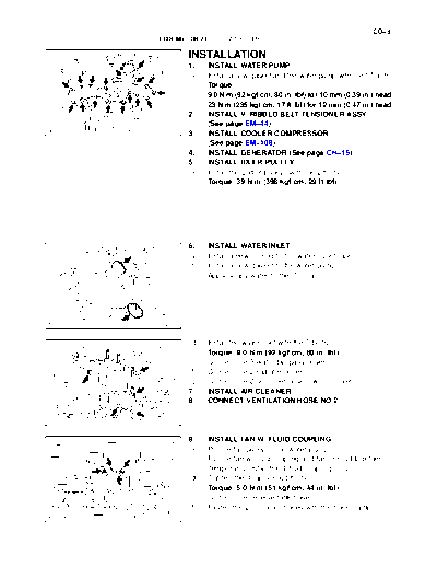
          1.    INSTALL WATER PUMP
          (a)   Install a new gasket and the water pump with the 17 bolts.
                Torque:
                9.0 Nm (92 kgfcm, 80 in.lbf) for 10 mm (0.39 in.) head
                23 Nm (235 kgfcm, 17 ftlbf) for 12 mm (0.47 in.) head
          2.    INSTALL V-RIBBED BELT TENSIONER ASSY
                (See page EM-44)
 A22973
          3.    INSTALL COOLER COMPRESSOR
                (See page EM-108)
          4.    INSTALL GENERATOR (See page CH-15)
          5.    INSTALL IDLER PULLEY
          (a)   Install the 2 idler pulleys with the 2 bolts.
                Torque: 39 Nm (398 kgfcm, 29 ftlbf)


          6.    INSTALL WATER INLET
          (a)   Install a new O-ring to the water outlet pipe.
          (b)   Install a new gasket to the water pump.
          (c)   Apply soapy water to the O-ring.


 A23120


          (d)   Install the water inlet with the 5 bolts.
                Torque: 9.0 Nm (92 kgfcm, 80 in.lbf)
          (e)   Connect the 5 water by-pass hoses.
          (f)   Connect the 2 radiator hoses.
          (g)   Connect the 2 oil cooler hoses (w/ oil cooler).
          7.    INSTALL AIR CLEANER
          8.    CONNECT VENTILATION HOSE NO.2

 A23121


          9.    INSTALL FAN W/ FLUID COUPLING
          (a)   Put the fan pulley to the water pump.
          (b)   Put the fan w/ fluid coupling and fan shroud together.
          (c)   Temporarily install the 4 fluid coupling nuts.
          (d)   Tighten the 4 fan shroud bolts.
                Torque: 5.0 Nm (51 kgfcm, 44 in.lbf)
          (e)   Connect the reserve tank hose.
          (f)   Fasten the 2 oil cooler hoses with the hose clamp.
 A23114
CO-10
        COOLING (1GR-FE)   -   WATER PUMP

                 10.   INSTALL FAN AND GENERATOR V BELT
                       (See page EM-89)
                 11.   FULLY TIGHTEN FAN W/ FLUID COUPLING
                 (a)   Tighten the 4 fluid coupling bolts.
                       Torque: 21 Nm (214 kgfcm, 15 ftlbf)
                 12.   ADD ENGINE COOLANT (See page CO-2)
                 13.   CHECK FOR ENGINE COOLANT LEAKS
                 14.   INSTALL ENGINE UNDER COVER
                 (a)   Install the engine under cover with the 4 bolts.
                       Torque: 29 Nm (296 kgfcm, 21 ftlbf)
                 15.   INSTALL V-BANK COVER
                 (a)   Install the V-bank cover with the 2 nuts.
                       Torque: 9.8 Nm (100 kgfcm, 87 in.lbf)
                 16.   RECHECK ENGINE COOLANT LEVEL
                 17.   FILL WITH ENGINE COOLANT
                 18.   START ENGINE AND CHECK FOR ENGINE COOLANT
                       LEAKS
                 19.   RECHECK ENGINE COOLANT LEVEL
◦ Jabse Service Manual Search 2026 ◦ Jabse Pravopis ◦ onTap.bg ◦ Other service manual resources online : Fixya ◦ eServiceinfo