Service Manuals, User Guides, Schematic Diagrams or docs for : . Car Manuals Toyota Tundra 2000-2006 Approved 04-06 techinfo.toyota.com ileaf 06toyrm 06toypdf 06rmsrc 06tundra bo inspan remo
<< Back | HomeMost service manuals and schematics are PDF files, so You will need Adobre Acrobat Reader to view : Acrobat Download Some of the files are DjVu format. Readers and resources available here : DjVu Resources
For the compressed files, most common are zip and rar. Please, extract files with Your favorite compression software ( WinZip, WinRAR ... ) before viewing. If a document has multiple parts, You should download all, before extracting.
Good luck. Repair on Your own risk. Make sure You know what You are doing.
Image preview - the first page of the document
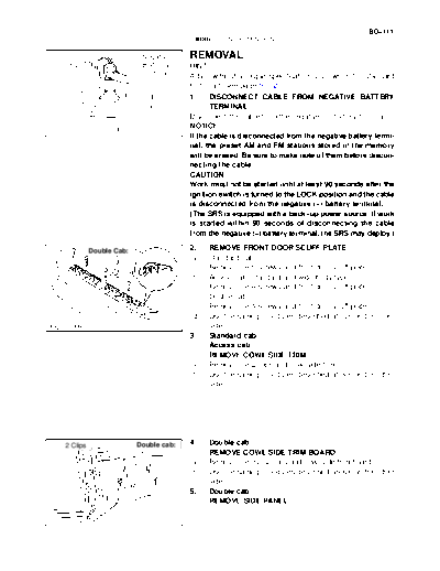
>> Download remo documenatation <<
Text preview - extract from the document
                                                                                               BO-111
                                           BODY   -   INSTRUMENT PANEL
                                                                                                 BO4QF-04


                         Negative        REMOVAL
                         Battery         HINT:
                         Terminal
                                         A bolt without a torque specification is shown in the standard
                                         bolt chart (see page SS-2).
                                         1.     DISCONNECT CABLE FROM NEGATIVE BATTERY
                                                TERMINAL
                                         Disconnect the cable from the negative (-) battery terminal.
                                         NOTICE:
                                BO4111
                                         If the cable is disconnected from the negative battery termi-
                                         nal, the preset AM and FM stations stored in the memory
                                         will be erased. Be sure to make note of them before discon-
                                         necting the cable.
                                         CAUTION:
                                         Work must not be started until at least 90 seconds after the
                                         ignition switch is turned to the LOCK position and the cable
                                         is disconnected from the negative (-) battery terminal.
                                         (The SRS is equipped with a back-up power source. If work
                                         is started within 90 seconds of disconnecting the cable
                                         from the negative (-) battery terminal, the SRS may deploy.)

          Double Cab:                    2.    REMOVE FRONT DOOR SCUFF PLATE
                                         (a)   Standard cab:
                                               Remove the 5 screws and front door scuff plate.
                                         (b)   Access cab (standard and wide body type):
                                               Remove the 4 screws and front door scuff plate.
                                         (c)   Double cab:
                                               Remove the 4 screws and front door scuff plate.
                                         (d)   Use the same procedures described above on the other
Claw                            H24383         side.
                                         3.    Standard cab:
                                               Access cab:
                                               REMOVE COWL SIDE TRIM
                                         (a)   Remove the 2 clips and cowl side trim.
                                         (b)   Use the same procedures described above on the other
                                               side.


2 Clips                 Double cab:      4.    Double cab:
                                               REMOVE COWL SIDE TRIM BOARD
                                         (a)   Remove the nut, 2 clips and cowl side trim board.
                                         (b)   Use the same procedures described above on the other
                                               side.
                                         5.    Double cab:
                                               REMOVE SIDE PANEL

                                H16716
BO-112
                             BODY   -   INSTRUMENT PANEL

                           6.    REMOVE ASSIST GRIPS
                           (a) Using a screwdriver, remove the plugs.
                           HINT:
                           Tape the screwdriver tip before use.
                           (b) Driver side:
                                 Using a torx
◦ Jabse Service Manual Search 2026 ◦ Jabse Pravopis ◦ onTap.bg ◦ Other service manual resources online : Fixya ◦ eServiceinfo