Service Manuals, User Guides, Schematic Diagrams or docs for : . Car Manuals Toyota Tundra 2000-2006 Approved 04-06 techinfo.toyota.com ileaf 06toyrm 06toypdf 06rmsrc 06tundra di ata750ea diasys
<< Back | HomeMost service manuals and schematics are PDF files, so You will need Adobre Acrobat Reader to view : Acrobat Download Some of the files are DjVu format. Readers and resources available here : DjVu Resources
For the compressed files, most common are zip and rar. Please, extract files with Your favorite compression software ( WinZip, WinRAR ... ) before viewing. If a document has multiple parts, You should download all, before extracting.
Good luck. Repair on Your own risk. Make sure You know what You are doing.
Image preview - the first page of the document
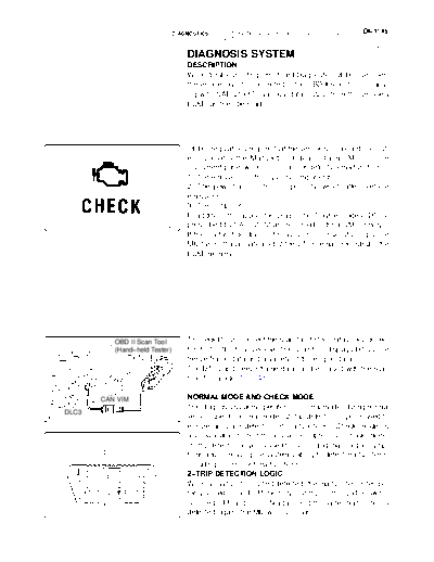
>> Download diasys documenatation <<
Text preview - extract from the document
                                      DIAGNOSTICS   -   AUTOMATIC TRANSMISSION (A750E/A750F for    DI-1145
                                                        2UZ-FE)
                                                                                                      DIDWD-01


                                          DIAGNOSIS SYSTEM
                                          DESCRIPTION
                                          When troubleshooting On-Board Diagnostic (OBD II) vehicles,
                                          the vehicle must be connected to the OBD II scan tool (comply-
                                          ing with SAE J1987). Various data output from the vehicle's
                                          ECM can then be read.


                                          OBD II regulations require that the vehicle's on-board comput-
                                          er illuminates the Malfunction Indicator Lamp (MIL) on the
                                          instrument panel when the computer detects a malfunction in:
                                          1) The emission control system/components
                                          2) The powertrain control components (which affect vehicle
                                          emissions)
                                          3) The computer
                                          In addition, the applicable Diagnostic Trouble Codes (DTCs)
                                D14150    prescribed by SAE J2012 are recorded in the ECM memory.
                                          If the malfunction does not reoccur in 3 consecutive trips, the
                                          MIL turns off automatically but the DTCs remain recorded in the
                                          ECM memory.


                 OBD II Scan Tool         To check DTCs, connect the scan tool to the Data Link Connec-
                 (Hand-held Tester)       tor 3 (DLC3) of the vehicle. The scan tool displays DTCs, the
                                          freeze frame data and a variety of the engine data.
                                          The DTCs and freeze frame data can be erased with the scan
                                          tool (See page DI-1148).

             CAN VIM                      NORMAL MODE AND CHECK MODE
                                          The diagnosis system operates in "normal mode" during normal
DLC3
                                D13872    vehicle use. In normal mode, "2-trip detection logic" is used to
                                          ensure accurate detection of malfunctions. "Check mode" is
                                          also available to technicians as an option. In check mode,
                                          "1-trip detection logic" is used for simulating malfunction symp-
              DLC3                        toms and increasing the system's ability to detect malfunctions,
                                          including intermittent malfunctions.
       1 2 3 4 5 6 7 8                    2-TRIP DETECTION LOGIC
                                          When a malfunction is first detected, the malfunction is tempo-
       9 10 11 12 1314 1516               rarily stored in the ECM memory (1st trip). If the ignition switch
                                          is turned OFF and then ON again, and the same malfunction is
                                D14151    detected again, the MIL will illuminate.
DI-1146                                     DIAGNOSTICS       -   AUTOMATIC TRANSMISSION (A750E/A750F for
                                                                  2UZ-FE)

                                                   FREEZE FRAME DATA
                                                   Freeze frame data records the engine conditions (fuel system,
                                                   calculated load, engine coolant temperature, fuel trim, engine
                                                   speed, vehicle speed, etc.) when a malfunction is detected.
                                                   When troubleshooting, freeze frame data can help determine
                                                   if the vehicle was running or stopped, if the engine was warmed
                                                   up or not, if the air/fuel ratio was Lean or Rich, and other data
                                                   from the time the malfunction occurred.


                                                   The hand-held tester records freeze frame data in five different
                          DTC was set.
                                                   instances: 1) 3 times before the DTC is set, 2) once when the
                                   B
                                                   DTC is set, and 3) once after the DTC is set. These data can be
          0.5 sec. 0.5 sec. 0.5 sec.               used to simulate the vehicle's condition around the time when
                                                   the malfunction occurred. The data may help find the cause of
                                                   the malfunction, or judge if the DTC is being caused by a tempo-
          L        L        L     L                rary malfunction or not.
                               L
 L : Freeze frame data which can be read
                                         D14152


                                                   DLC3 (Data Link Connector 3)
                                                   The vehicle's ECM uses the ISO 15765-4 for communication
                     DLC3                          protocol. The terminal arrangement of the DLC3 complies with
                                                   SAE J1962 and matches the ISO 15765-4 format.
              1 2 3 4 5 6 7 8                      HINT:
                                                   Connect the cable of the hand-held tester to the DLC3, turn the
              9 10 11 12 1314 1516                 ignition switch ON and attempt to use the hand-held tester. If
                                                   the screen displays UNABLE TO CONNECT TO VEHICLE, a
                                         D14151    problem exists in the vehicle side or the tester side.
                                                   If the communication is normal when the tool is connected to
                                                   another vehicle, inspect the DLC3 on the original vehicle.
                                                   If the communication is still impossible when the tool is con-
                                                   nected to another vehicle, the problem is probably in the tool it-
                                                   self. Consult the Service Department listed in the tool's instruc-
                                                   tion manual.
      Symbol             Terminal No.             Name            Reference terminal       Result             Condition
       SIL                    7              Bus "+" line         5 - Signal ground    Pulse generation   During transmission
       CG                     4            Chassis ground           Body ground           Below 1               Always
       SG                     5             Signal ground           Body ground           Below 1               Always
       BAT                   16            Battery positive         Body ground           11 to 14 V            Always
                                          HIGH-level CAN
      CANH                    6                                         CANL              54 to 69          IG switch OFF
                                             bus line
                                          HIGH-level CAN
      CANH                    6                                    Battery positive    1 M or higher        IG switch OFF
                                             bus line
                                          HIGH-level CAN
      CANH                    6                                          CG             1 k or higher       IG switch OFF
                                             bus line
                                           LOW-level CAN
      CANL                   14                                    Battery positive    1 M or higher        IG switch OFF
                                              bus line
                                           LOW-level CAN
      CANL                   14                                          CG             1 k or higher       IG switch OFF
                                              bus line
DIAGNOSTICS   -   AUTOMATIC TRANSMISSION (A750E/A750F for    DI-1147
                  2UZ-FE)

    CHECK BATTERY VOLTAGE
           Battery voltage: 11 to 14 V
    If voltage is below 11 V, replace the battery before proceeding.

    CHECK MIL
    (a) Check that the MIL illuminates when turning the ignition
           switch ON.
    If the MIL does not illuminate, there is a problem in the MIL cir-
    cuit (refer to MIL CIRCUIT on page DI-940)
    (b) When the engine is started, the MIL should turn off.

    ALL READINESS
    For this vehicle, using the hand-held tester allows readiness
    codes corresponding to all DTCs to be read. When diagnosis
    (normal or malfunctioning) has been complete, readiness
    codes are set. Enter the following menus: ENHANCED OBD II
    / MONITOR STATUS on the hand-held tester.
◦ Jabse Service Manual Search 2026 ◦ Jabse Pravopis ◦ onTap.bg ◦ Other service manual resources online : Fixya ◦ eServiceinfo