Service Manuals, User Guides, Schematic Diagrams or docs for : . Car Manuals Toyota Tundra 2000-2006 Approved 04-06 techinfo.toyota.com ileaf 06toyrm 06toypdf 06rmsrc 06tundra em1grfe valcle insp
<< Back | HomeMost service manuals and schematics are PDF files, so You will need Adobre Acrobat Reader to view : Acrobat Download Some of the files are DjVu format. Readers and resources available here : DjVu Resources
For the compressed files, most common are zip and rar. Please, extract files with Your favorite compression software ( WinZip, WinRAR ... ) before viewing. If a document has multiple parts, You should download all, before extracting.
Good luck. Repair on Your own risk. Make sure You know what You are doing.
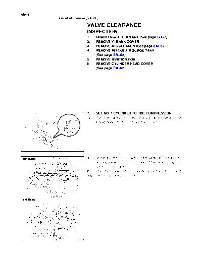
Image preview - the first page of the document
>> Download insp documenatation <<
Text preview - extract from the document
EM-4
ENGINE MECHANICAL (1GR-FE) - VALVE CLEARANCE
VALVE CLEARANCE EM1XG-01
INSPECTION
1. DRAIN ENGINE COOLANT (See page CO-2)
2. REMOVE V-BANK COVER
3. REMOVE AIR CLEANER (See page EM-62)
4. REMOVE INTAKE AIR SURGE TANK
(See page EM-62)
5. REMOVE IGNITION COIL
6. REMOVE CYLINDER HEAD COVER
(See page EM-62)
7. SET NO. 1 CYLINDER TO TDC/COMPRESSION
(a) Turn the crankshaft pulley, and align its groove with the
timing mark "0" of the timing chain cover.
A22800
RH Bank Timing Marks (b) Check that the timing marks of the camshaft timing gears
are aligned with the timing marks of the bearing caps as
shown in the illustration.
If not, turn the crankshaft 1 complete revolution (360 _) and
align the timing marks as above.
Timing Marks
LH Bank
Timing Marks A22801
EM-5
ENGINE MECHANICAL (1GR-FE) - VALVE CLEARANCE
8. INSPECT VALVE CLEARANCE
RH Bank: 3 3
(a) Check the valves indicated in the illustration.
(1) Using a feeler gauge, measure the clearance be-
EX tween the valve lifter and camshaft.
Valve clearance (Cold):
IN Intake: 0.15 to 0.25 mm (0.006 to 0.010 in.)
Exhaust: 0.29 to 0.39 mm (0.011 to 0.015 in.)
(2) Record the out-of-specification valve clearance
1 1 measurements. They will be used later to determine
LH Bank: Front 6 6 the required replacement valve lifter.
IN
EX
2 2
A22802
(b) Turn the crankshaft 2/3 of a revolution (240_), and check
RH Bank: 5 5
the valves indicated in the illustration.
(1) Using a feeler gauge, measure the clearance be-
EX tween the valve lifter and camshaft.
Valve clearance (Cold):
Intake: 0.15 to 0.25 mm (0.006 to 0.010 in.)
IN
Exhaust: 0.29 to 0.39 mm (0.011 to 0.015 in.)
(2) Record the out-of-specification valve clearance
3 3 measurements. They will be used later to determine
LH Bank: Front the required replacement valve lifter.
2 2
IN
EX
4 4
A22803
EM-6
ENGINE MECHANICAL (1GR-FE) - VALVE CLEARANCE
(c) Turn the crankshaft 2/3 of a revolution (240_), and check
RH Bank: 1 1
the valves indicated in the illustration.
(1) Using a feeler gauge, measure the clearance be-
EX tween the valve lifter and camshaft.
Valve clearance (Cold):
Intake: 0.15 to 0.25 mm (0.006 to 0.010 in.)
IN
Exhaust: 0.29 to 0.39 mm (0.011 to 0.015 in.)
(2) Record the out-of-specification valve clearance
5 5 measurements. They will be used later to determine
LH Bank: Front the required replacement valve lifter.
4 4
IN
EX
6 6
A22804
9. ADJUST VALVE CLEARANCE
(a) Set the No. 1 cylinder to the TDC/compression.
(1) Turn the crankshaft pulley, and align the notch with
the timing mark "0" of the timing chain cover.
A22800
RH Bank Timing Marks (2) Check that the timing marks of the camshaft timing
gears are aligned with the timing marks of the bear-
ing caps as shown in the illustration.
If not, turn the crankshaft 1 complete revolution (360 _) and
align the timing marks as above.
Timing Marks
LH Bank
Timing Marks A22801
EM-7
ENGINE MECHANICAL (1GR-FE) - VALVE CLEARANCE
(3)Place paint marks on the No. 1 chain links that cor-
Paint Marks
respond with the timing marks of the camshaft tim-
ing gears.
(b) Remove the chain tensioner No. 1.
NOTICE:
S Never rotate the crankshaft with the chain tensioner
removed.
Timing Marks S When rotating the camshaft with the timing chain re-
A22805 moved, turn the crankshaft counterclockwise 40 _
from the TDC first.
(1) Remove the 4 bolts, timing chain cover plate and
gasket.
A22806
(2) While rotating the stopper plate of the tensioner up-
ward, push in the plunger of the chain tensioner as
Push
shown in the illustration.
(3) While rotating the stopper plate of the tensioner
downward, insert a bar of 3.5 mm (0.138 in.) into
the holes in the stopper plate and tensioner to fix the
stopper plate.
Stopper
Stopper Plate (4) Remove the 2 bolts and chain tensioner No.1.
Plate
A22807 (c) Remove the No. 2 camshaft.
NOTICE:
As the thrust clearance of the camshaft is small, the cam-
shaft must be kept level while it is being removed. If the
camshaft is not kept level, the portion of the cylinder head
which receives the shaft thrust may crack or be damaged,
causing the camshaft to seize or break. To avoid this, the
following steps should be carried out.
(1) While raising up the chain tensioner No. 2, insert a
pin of 1.0 mm (0.039 in.) into the hole to fix it.
Raise
A22808
EM-8
ENGINE MECHANICAL (1GR-FE) - VALVE CLEARANCE
(2) Hold the hexagonal portion of the No. 2 camshaft
with a wrench, and remove the camshaft timing
sprocket set bolt.
NOTICE:
Be careful not to damage the cylinder head and valve lifter
with the wrench.
(3) Separate the camshaft timing sprocket from the No.
2 camshaft.
A22809
(4) Rotate the camshaft counterclockwise using the
wrench so that the cam lobes of the No. 1 cylinder
face upward as shown in the illustration.
A22810
(5) Using several steps, loosen and remove the 8 bear-
ing cap bolts uniformly in the sequence as shown in
the illustration.
(6) Remove the 4 bearing caps and No. 2 camshaft.
2 4 8 6
1 3 7 5
A22811
(d) Remove the chain tensioner No. 2.
(1) Remove the chain tensioner No. 2 bolt, and then re-
move the chain tensioner No. 2 and camshaft timing
sprocket.
(e) Remove the camshaft.
NOTICE:
As the thrust clearance of the camshaft is small, the cam-
shaft must be kept level while it is being removed. If the
A22812 camshaft is not kept level, the portion of the cylinder head
which receives the shaft thrust may crack or be damaged,
causing the camshaft to seize or break. To avoid this, the
following steps should be carried out.
EM-9
ENGINE MECHANICAL (1GR-FE) - VALVE CLEARANCE
(1) Hold the hexagonal portion of the No. 1 camshaft
with a wrench, and loosen the camshaft timing gear
assembly set bolt.
NOTICE:
S Be careful not to damage the cylinder head and valve
lifter with the wrench.
S Do not disassemble the camshaft timing gear assem-
bly.
A22813
(2) Slide the camshaft timing gear assembly and sepa-
rate the No. 1 chain from the camshaft timing gear
sprocket.
Slide
A22814
(3) Rotate the No. 1 camshaft counterclockwise using
a wrench so that the cam lobes of No. 1 cylinder
face upward as shown in the illustration.
A22815
(4) Using several steps, loosen and remove the 8 bear-
ing cap bolts uniformly in the sequence as shown in
5 the illustration.
1 3 7
(5) Remove the 4 bearing caps.
2 4 8 6
A22816
(6) Remove the camshaft timing gear assembly set bolt
with the No. 1 camshaft lifted up, and then remove
the No. 1 camshaft and camshaft timing gear as-
sembly w/ No. 2 chain.
A22817
EM-10
ENGINE MECHANICAL (1GR-FE) - VALVE CLEARANCE
(7) Tie the No. 1 chain with a string as shown in the il-
lustration.
NOTICE:
Be careful not to drop anything inside the timing chain cov-
er.
(f) Remove the No. 4 camshaft.
NOTICE:
As the thrust clearance of the camshaft is small, the cam-
A22818 shaft must be kept level while it is being removed. If the
camshaft is not kept level, the portion of the cylinder head
which receives the shaft thrust may crack or be damaged,
causing the camshaft to seize or break. To avoid this, the
following steps should be carried out.
(1) While pushing down the chain tensioner No. 2, in-
Push sert a pin of 1.0 mm (0.039 in.) into the hole to fix
it.
A22819
(2) Hold the hexagonal portion of the No. 4 camshaft
with a wrench, and remove the camshaft timing
sprocket set bolt.
NOTICE:
Be careful not to damage the cylinder head and valve lifter
with the wrench.
(3) Separate the camshaft timing sprocket from the No.
4 camshaft.
A22820
(4) Using several steps, loosen and remove the 8 bear-
ing cap bolts uniformly in the sequence as shown in
the illustration.
(5) Remove the 4 bearing caps and No. 4 camshaft.
6 8 4 2
5 7 3 1
A22821
EM-11
ENGINE MECHANICAL (1GR-FE) - VALVE CLEARANCE
(g) Remove the chain tensioner No. 2.
(1) Remove the chain tensioner No. 3 bolt, and then re-
move the chain tensioner No. 3 and camshaft timing
sprocket.
(h) Remove the No. 3 camshaft.
NOTICE:
As the thrust clearance of the camshaft is small, the cam-
shaft must be kept level while it is being removed. If the
A22822 camshaft is not kept level, the portion of the cylinder head
which receives the shaft thrust may crack or be damaged,
causing the camshaft to seize or break. To avoid this, the
following steps should be carried out.
(1) Using several steps, loosen and remove the 8 bear-
ing cap bolts uniformly in the sequence as shown in
5 the illustration.
7 3 1
(2) Remove the 4 bearing caps.
8 4 2
6
A22823
(3) Hold the No. 1 chain, and remove the No. 3 cam-
shaft, camshaft timing gear assembly and No. 2
chain.
A22824
(4) Tie the No. 1 chain with a string as shown in the il-
lustration.
NOTICE:
Be careful not to drop anything inside the timing chain cov-
er.
(i) Remove the valve lifters.
A22825
EM-12
ENGINE MECHANICAL (1GR-FE) - VALVE CLEARANCE
(j) Determine the size of the valve lifter to be installed ac-
cording to the following formulas or charts:
(1) Using a micrometer, measure the thickness of the
removed lifter.
(2) Calculate the thickness of a new lifter so that the
valve clearance comes within the specified value.
T: Thickness of removed lifter
A: Measured valve clearance
A01082 N: Thickness of new lifter
Intake:
N = T + (A - 0.20 mm (0.008 in.))
Exhaust:
N = T + (A - 0.30 mm (0.012 in.))
(3) Select a new lifter with a thickness as close as pos-
sible to the calculated value.
HINT:
Lifters are available in 35 sizes in increments of 0.020 mm
(0.0008 in.), from 5.060 mm (0.1992 in.) to 5.740 mm (0.2260
in.).
Valve Lifter Selection Chart (Intake)
Removed lifter
thickness
mm (in.)
Measured
clearance mm (in.)
ENGINE MECHANICAL (1GR-FE)
-
VALVE CLEARANCE
New Lifter Thickness mm (in.)
No. Thickness No. Thickness No. Thickness
Intake valve clearance (Cold):
0.15 to 0.25 mm (0.0059 to 0.0098 in.)
EXAMPLE:
The 5.250 mm (0.2067 in.) lifter is installed, and the
measured clearance is 0.400 mm (0.0158 in.).
Replace the 5.250 mm (0.2067 in.) shim with a new
No. 46 lifter.
EM-13
A22826
EM-14
Valve Lifter Selection Chart (Exhaust)
Removed lifter
thickness
mm (in.)
Measured
clearance mm (in.)
ENGINE MECHANICAL (1GR-FE)
-
VALVE CLEARANCE
New Lifter Thickness mm (in.)
No. Thickness No. Thickness No. Thickness
Exhaust valve clearance (Cold):
0.29 to 0.39 mm (0.0114 to 0.0154 in.)
EXAMPLE:
The 5.340 mm (0.2102 in.) lifter is installed, and the
measured clearance is 0.480 mm (0.0189 in.).
Replace the 5.340 mm (0.2102 in.) shim with a new
No. 48 lifter.
A22827
EM-15
ENGINE MECHANICAL (1GR-FE) - VALVE CLEARANCE
(k) Install the No. 3 camshaft.
NOTICE:
As the thrust clearance of the camshaft is small, the cam-
shaft must be kept level while it is being installed. If the
camshaft is not kept level, the portion of the cylinder head
which receives the shaft thrust may crack or be damaged,
causing the camshaft to seize or break. To avoid this, the
following steps should be carried out.
Mark Links (1) Align the mark link (yellow) with the timing mark
(2-dot mark) of the camshaft timing gear assembly
as shown in the illustration.
(2) Apply new engine oil to the thrust portions and jour-
nals of the camshafts.
Timing Marks
A22828
(3) Temporarily put the No. 1 chain on the No. 2 chain
of the camshaft timing gear assembly.
A22829
(4) Set the No. 3 camshaft onto the LH cylinder head
with the cam lobes of the No. 2 cylinder facing
downward as shown in the illustration.
A22830
(5) Install the 4 bearing caps in their proper locations.
(6) Apply a light coat of engine oil to the threads of the
bearing cap bolts.
A22831
EM-16
ENGINE MECHANICAL (1GR-FE) - VALVE CLEARANCE
(7) Install the 8 bearing cap bolts. Using several steps,
tighten the bolts uniformly in the sequence as
4 shown in the illustration.
2 6 8
Torque:
9.0 Nm (92 kgfcm, 80 in.lbf) for 10 mm (0.39 in.) head
1 5 7 24 Nm (245 kgfcm, 18 ftlbf) for 12 mm (0.47 in.) head
3
A22832
(8) Set the paint mark of the No. 1 chain between the
Paint Mark timing marks of the camshaft timing gear assembly.
Timing Marks
A22833
(l) Install the chain tensioner No. 2.
(1) While pushing in the tensioner, insert a pin of 1.0
mm (0.039 in.) into the hole to fix it.
Push
A22834
(2) Temporarily install the camshaft timing assembly
Mark Links
and chain tensioner No. 2 and align the mark links
(yellow) with the timing marks (1-dot mark and
2-dot mark) of the camshaft timing sprocket and
camshaft timing gear assembly.
(3) Tighten the chain tensioner No. 3 bolt.
Torque: 19 Nm (194 kgfcm, 14 ftlbf)
(m) Install the No. 4 camshaft.
Timing Marks A22835 NOTICE:
As the thrust clearance of the camshaft is small, the cam-
shaft must be kept level while it is being installed. If the
camshaft is not kept level, the portion of the cylinder head
which receives the shaft thrust may crack or be damaged,
causing the camshaft to seize or break. To avoid this, the
following steps should be carried out.
EM-17
ENGINE MECHANICAL (1GR-FE) - VALVE CLEARANCE
(1) Align the knock pin hole on the camshaft timing
sprocket with the knock pin of the No. 4 camshaft,
and insert the No. 4 camshaft into the camshaft tim-
ing sprocket.
(2) Temporarily install the camshaft timing sprocket set
bolt.
A22836
(3) Install the 4 bearing caps in their proper locations.
(4) Apply a light coat of engine oil to the threads and un-
der the heads of the bearing cap bolts.
A22837
(5) Install the 8 bearing cap bolts. Using several steps,
tighten the bolts uniformly in the sequence as
shown in the illustration.
Torque:
9.0 Nm (92 kgfcm, 80 in.lbf) for 10 mm (0.39 in.) head
3 1 5 7 24 Nm (245 kgfcm, 18 ftlbf) for 12 mm (0.47 in.) head
4 2 6 8
A22821
(6) Hold the hexagonal portion of the No. 4 camshaft
with a wrench, and tighten the camshaft timing
sprocket set bolt.
Torque: 100 Nm (1,020 kgfcm, 74 ftlbf)
(7) Remove the pin from the chain tensioner No. 2.
(n) Install the camshaft.
NOTICE:
As the thrust clearance of the camshaft is small, the cam-
A22820 shaft must be kept level while it is being installed. If the
camshaft is not kept level, the portion of the cylinder head
which receives the shaft thrust may crack or be damaged,
causing the camshaft to seize or break. To avoid this, the
following steps should be carried out.
EM-18
ENGINE MECHANICAL (1GR-FE) - VALVE CLEARANCE
Mark Links (1) Align the mark link (yellow) with the timing mark
(1-dot mark) of the camshaft timing gear assembly
as shown in the illustration.
(2) Apply new engine oil to the thrust portions and jour-
nals of the camshafts.
Timing Mark
A22838
(3) Temporarily put the No. 1 chain on the No. 2 chain
of the camshaft timing gear assembly.
A22839
(4) Align the knock pin hole on the camshaft timing gear
Knock Pin
assembly with the knock pin of the No. 1 camshaft,
and insert the No. 1 camshaft into the camshaft tim-
ing gear assembly.
(5) Temporarily install the camshaft timing gear assem-
bly set bolt.
A22840
(6) Set the No. 1 camshaft onto the RH cylinder head
with the cam lobes of the No. 1 cylinder facing
downward as shown in the illustration.
A22841
(7) Install the 4 bearing caps in their proper locations.
(8) Apply a light coat of engine oil to the threads and un-
der the heads of the bearing cap bolts.
A22842
EM-19
ENGINE MECHANICAL (1GR-FE) - VALVE CLEARANCE
(9) Install the 8 bearing cap bolts. Using several steps,
tighten the bolts uniformly in the sequence as
4 shown in the illustration.
8 6 2
Torque:
9.0 Nm (92 kgfcm, 80 in.lbf) for 10 mm (0.39 in.) head
7 5 1 3 24 Nm (245 kgfcm, 18 ftlbf) for 12 mm (0.47 in.) head
A22816
(10) Rotate the No. 1 camshaft clockwise using the hex-
Timing Marks
agonal portion of the No. 1 camshaft so that the tim-
ing mark of the camshaft timing gear assembly is
aligned with the timing mark of the camshaft bear-
ing cap.
A22843
(11) Align the paint mark of the No. 1 chain with the tim-
Paint Mark
ing mark of the camshaft timing gear assembly.
Timing Mark
A22844
(12) Hold the hexagonal portion of the No. 1 camshaft
with a wrench, and tighten the camshaft timing gear
assembly set bolt.
Torque: 100 Nm (1,020 kgfcm, 74 ftlbf)
A22813
(o) Install the chain tensioner No. 2.
(1) While pushing in the tensioner, insert a pin of 1.0
mm (0.039 in.) into the hole to fix it.
Push
A22900
EM-20
ENGINE MECHANICAL (1GR-FE) - VALVE CLEARANCE
Mark Links (2) Temporarily install the camshaft timing gear and
chain tensioner No. 2 and align the mark links (yel-
low) with the timing marks (1-dot mark) of the cam-
shaft timing gear assembly and camshaft timing
sprocket.
(3) Tighten the chain tensioner No. 2 bolt.
Torque: 19 Nm (194 kgfcm, 14 ftlbf)
(p) Install the No. 2 camshaft.
Timing Marks A22846 NOTICE:
As the thrust clearance of the camshaft is small, the cam-
shaft must be kept level while it is being installed. If the
camshaft is not kept level, the portion of the cylinder head
which receives the shaft thrust may crack or be damaged,
causing the camshaft to seize or break. To avoid this, the
following steps should be carried out.
(1) Set the No. 2 camshaft onto the RH cylinder head
with the cam lobes of No. 1 cylinder facing upward
as shown in the illustration.
A22847
(2) Install the 4 bearing caps in their proper locations.
(3) Apply a light coat of engine oil to the threads and un-
der the heads of the bearing cap bolts.
A22848
(4) Install the 8 bearing cap bolts. Using several steps,
tighten the bolts uniformly in the sequence as
shown in the illustration.
Torque:
9.0 Nm (92 kgfcm, 80 in.lbf) for 10 mm (0.39 in.) head
7 5 1 3
24 Nm (245 kgfcm, 18 ftlbf) for 12 mm (0.47 in.) head
8 6 2 4
A22811
EM-21
ENGINE MECHANICAL (1GR-FE) - VALVE CLEARANCE
(5) Rotate the No. 2 camshaft clockwise using a
wrench so that the knock pin of the No. 2 camshaft
is aligned with the knock pin hole of the camshaft
timing sprocket.
Knock Pin
A22849
(6) Hold the hexagonal portion of the No. 2 camshaft
with a wrench, and install the camshaft timing
sprocket set bolt.
Torque: 100 Nm (1,020 kgfcm, 74 ftlbf)
(7) Remove the pin from the chain tensioner No. 2.
A22809
(q) Install the chain tensioner No. 1.
(1) While turning the stopper plate of the tensioner
clockwise, push in the plunger of the tensioner as
shown in the illustration.
(2) While turning the stopper plate of the tensioner
counterclockwise, insert a bar of 3.5 mm (0.138
in.) into the holes on the stopper plate and tensioner
Stopper Plate to fix the stopper plate.
Stopper Plate Push (3) Install the chain tensioner with the 2 bolts.
A22850
Torque: 10 Nm (102 kgfcm, 7 ft◦ Jabse Service Manual Search 2026 ◦ Jabse Pravopis ◦ onTap.bg ◦ Other service manual resources online : Fixya ◦ eServiceinfo