Service Manuals, User Guides, Schematic Diagrams or docs for : . Car Manuals Toyota Tundra 2000-2006 Approved 04-06 techinfo.toyota.com ileaf 06toyrm 06toypdf 06rmsrc 06tundra em1grfe cylblo disa

<< Back | Home

Most service manuals and schematics are PDF files, so You will need Adobre Acrobat Reader to view : Acrobat Download Some of the files are DjVu format. Readers and resources available here : DjVu Resources
For the compressed files, most common are zip and rar. Please, extract files with Your favorite compression software ( WinZip, WinRAR ... ) before viewing. If a document has multiple parts, You should download all, before extracting.
Good luck. Repair on Your own risk. Make sure You know what You are doing.


Image preview - the first page of the document
disa


>> Download disa documenatation <<

Text preview - extract from the document
EM-112
               ENGINE MECHANICAL (1GR-FE)   -   CYLINDER BLOCK
                                                                                              EM1XZ-01


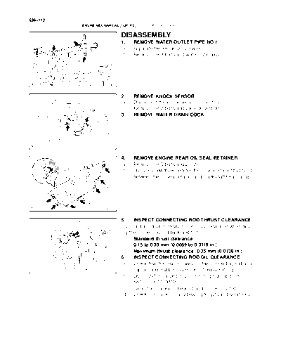
                                   DISASSEMBLY
                                   1.    REMOVE WATER OUTLET PIPE NO.1
                                   (a)   Separate the knock sensor wire.
                                   (b)   Remove the 3 bolts and water outlet pipe.


                          A22979


                                   2.    REMOVE KNOCK SENSOR
                                   (a)   Disconnect the knock sensor connectors.
                                   (b)   Remove the 2 bolts and 2 knock sensors.
                                   3.    REMOVE WATER DRAIN COCK


                          A22980


                                   4.    REMOVE ENGINE REAR OIL SEAL RETAINER
         Pry                       (a)   Remove the 5 bolts and 2 nuts.
                                   (b)   Using a screwdriver, remove the oil seal retainer by prying
                                         between the oil seal retainer and crankshaft bearing cap.


                          A22981


                                   5.    INSPECT CONNECTING ROD THRUST CLEARANCE
                                   Using a dial indicator, measure the thrust clearance while mov-
                                   ing the connecting rod back and forth.
                                         Standard thrust clearance:
                                         0.15 to 0.30 mm (0.0059 to 0.0118 in.)
                                         Maximum thrust clearance: 0.35 mm (0.0138 in.)
                                   6.    INSPECT CONNECTING ROD OIL CLEARANCE
                                   (a) Check that the matchmarks on the connecting rod and
                          A23021         cap are aligned to ensure correct reassembling.
                                   (b) Using SST, remove the 2 connecting rod cap bolts.
                                         SST 09011-38121
                                   (c) Clean the crank pin, bearing and connecting rod.
                                   (d) Check the crank pin and bearing for pits and scratches.
                                                                                                  EM-113
                      ENGINE MECHANICAL (1GR-FE)   -   CYLINDER BLOCK

                                          (e)   Lay a strip of Plastigage across the crank pin.
  Plastigage


                                 A23022


                                          (f)   Check that the protrusion of the connecting rod cap is fac-
                                                ing the correct direction.
                                          (g)   Apply a light coat of engine oil to the threads of the con-
                                                necting rod cap bolts.


Protrusion


                                 A23023


                                          (h)   Using SST, tighten the bolts alternately to the specified
                                                torque.
                                                SST 09011-38121
                                                Torque: 25 Nm (250 kgfcm, 18 ftlbf)


                                 A23024


               Painted Mark               (i)  Mark the front side of each connecting cap bolt with paint.
90_                                       (j)  Retighten the cap bolts 90_ as shown in the illustration.
                                          NOTICE:
 Front       90_                          Do not turn the crankshaft.
                                          (k) Remove the 2 bolts, connecting rod cap and lower bear-
                                               ing.


                                 A23025


                                          (l) Measure the Plastigage at its widest point.
                                              Standard oil clearance:
                                              0.026 to 0.046 mm (0.0010 to 0.0018 in.)
                                              Maximum oil clearance: 0.066 mm (0.0025 in.)
                                          NOTICE:
                                          Completely remove the Plastigage.


                                 A23026
EM-114
                   ENGINE MECHANICAL (1GR-FE)    -     CYLINDER BLOCK

Number Mark                            (m)     If replacing a bearing, replace it with one that has the
              Number Mark
                                               same number marked on the connecting rod. There are
                                               4 sizes of standard bearings, marked "1 ", "2", "3" and "4"
                                               accordingly.
                                       HINT:
                                       Standard bearing center wall thickness
                                                Mark                                mm (in.)
                                                "1"                     1.484 to 1.487 (0.0584 to 0.0585)
                              A23027            "2"                     1.487 to 1.490 (0.0585 to 0.0587)
                                                "3"                     1.490 to 1.493 (0.0587 to 0.0588)
                                                "4"                     1.493 to 1.496 (0.0588 to 0.0589)


                                       7.      REMOVE PISTON W/CONNECTING ROD
                                       (a)     Using a ridge reamer, remove all the carbon from the top
                                               of the cylinder.
                                       (b)     Push in the piston w/ connecting rod and upper bearing
                                               through the top of the cylinder block.
                                       HINT:
                                       S       Keep the bearings, connecting rod and cap together.
                                       S       Arrange the piston and connecting rod assemblies in the
                              A23028           correct order.
                                       8.      REMOVE CONNECTING ROD BEARING
                                       9.      REMOVE PISTON RING SET
                                       (a)     Using a piston ring expander, remove the 2 compression
                                               rings.
                                       (b)     Remove the 2 side rails and oil ring by hand.


                              A23029


                                       10. REMOVE PISTON PIN HOLE SNAP RING
                                       Using a screwdriver, pry out the 2 snap rings.


                              A23030
                                                                                                      EM-115
                       ENGINE MECHANICAL (1GR-FE)       -   CYLINDER BLOCK

                                              11.     REMOVE PISTON PIN
80_C
                                              (a)     Gradually heat the piston to approx. 80_C (176_F).


                                     A23031


                                              (b)     Using a plastic-faced hammer and brass bar, lightly tap
                                                      out the piston pin and remove the connecting rod.
                                              HINT:
                                              S       The piston and pin are a matched set.
                                              S       Arrange the pistons, pins, rings, connecting rods and
                                                      bearings in the correct order.


                                     A23032


                                              12.    INSPECT CRANKSHAFT THRUST CLEARANCE
                                              (a)    Using a dial indicator, measure the thrust clearance while
                                                     prying the crankshaft back and forth with a screwdriver.
                                                     Standard thrust clearance:
                                                     0.04 to 0.24 mm (0.0016 to 0.0094 in.)
                                                     Maximum thrust clearance: 0.30 mm (0.0118 in.)
                                              If the thrust clearance is greater than the maximum, replace the
                                              pair of the thrust washers or the crankshaft.
                                     A23033   HINT:
                                              Thrust washer thickness is 1.93 to 1.98 mm (0.0760 to 0.0780
                                              in.)


                                              13.     REMOVE CRANKSHAFT
                   5
           8                                  (a)     Using several steps, uniformly loosen and remove the 8
       7                                              main bearing cap bolts and seal washers in the sequence
                                 2                    as shown in the illustration.
                             3
 6
                        4
               1


                                     A23034
EM-116
                        ENGINE MECHANICAL (1GR-FE)    -   CYLINDER BLOCK

                                              (b)   Using several steps, uniformly loosen and remove the 16
                                                    main bearing cap bolts in the sequence as shown in the
                        4
                    8      12                       illustration.
               6       16 11
                   14 15         3
         2    10 13          7
                        5
             9
                  1


                                     A23035


                                              (c) Using a screwdriver, pry out the main bearing caps. Re-
                                                  move the 4 main bearing caps and lower bearings.
                                              NOTICE:
                                               S  Pull up the main bearing cap while turning it little by
                                                  little to the right and the left.


                                     A23036


                                              S     Be careful not to damage the joint surface of the cylin-
                                                    der block and the main bearing cap.
     Main Bearing Cap                         14.   REMOVE CRANKSHAFT THRUST WASTER SET
                                              15.   REMOVE CRANKSHAFT BEARING


                             Cylinder
                             Block
                                     A23037


                                              16. REMOVE OIL NOZZLE
                                              Using a 5 mm socket hexagon wrench, remove the 3 oil
                                              nozzles.


                                     A23038


◦ Jabse Service Manual Search 2026 ◦ Jabse PravopisonTap.bg ◦ Other service manual resources online : FixyaeServiceinfo