Service Manuals, User Guides, Schematic Diagrams or docs for : . Car Manuals Toyota Tundra 2000-2006 Approved 04-06 techinfo.toyota.com ileaf 06toyrm 06toypdf 06rmsrc 06tundra em1grfe cylblo reas

<< Back | Home

Most service manuals and schematics are PDF files, so You will need Adobre Acrobat Reader to view : Acrobat Download Some of the files are DjVu format. Readers and resources available here : DjVu Resources
For the compressed files, most common are zip and rar. Please, extract files with Your favorite compression software ( WinZip, WinRAR ... ) before viewing. If a document has multiple parts, You should download all, before extracting.
Good luck. Repair on Your own risk. Make sure You know what You are doing.


Image preview - the first page of the document
reas


>> Download reas documenatation <<

Text preview - extract from the document
EM-128
                      ENGINE MECHANICAL (1GR-FE)   -   CYLINDER BLOCK
                                                                                                      EM1Y2-01


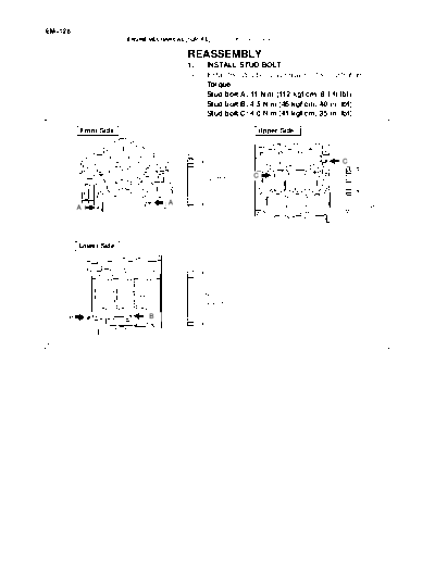
                                         REASSEMBLY
                                         1.    INSTALL STUD BOLT
                                         (a)   Install the stud bolts as shown in the illustration.
                                               Torque:
                                               Stud bolt A: 11 Nm (112 kgfcm, 8.1 ftlbf)
                                               Stud bolt B: 4.5 Nm (46 kgfcm, 40 in.lbf)
                                               Stud bolt C: 4.0 Nm (41 kgfcm, 35 in.lbf)

         Front Side                                              Upper Side


                                                                                           C

                                               42 mm           C
                                               (1.65 in.)

                                   A                                                             23 mm
         A                                                                                       (0.91 in.)
                                                                                            M6


         Lower Side


                                               56 mm
                                               (2.20 in.)

     B                       B


                                                                                                       A23062
                                                                                                             EM-129
                      ENGINE MECHANICAL (1GR-FE)         -    CYLINDER BLOCK

                                              2.      INSTALL STRAIGHT PIN
                                              (a)     Using a plastic-faced hammer, tap in the straight pin.
                                                      Standard protrusion:
                                                      Pin A: 22.5 to 23.5 mm (0.886 to 0.925 in.)
                                                      Pin B: 10.5 to 11.5 mm (0.413 to 0.453 in.)
                                                      Pin C: 8.5 to 9.5 mm (0.335 to 0.374 in.)
                                                      Pin D: 5.5 to 6.5 mm (0.217 to 0.256 in.)


Front Side                                                          Front Side


                                     10 mm
                                     (0.39 in.)
              A                                                                                       4 mm
                                                                                                      (0.16 in.)
                                                                                             D
                                                 36 mm             D
                                                 (1.42 in.)
                                                                    Protrusion Height: 5.5 to 6.5 mm      12 mm
    Protrusion Height: 22.5 to 23.5 mm
                      (0.886 to 0.925 in.)                          Rear Side        (0.217 to 0.256 in.) (0.47 in.)
Rear Side
      B
                                    10 mm
                                    (0.39 in.)                                                       4 mm
                                                                                                     (0.16 in.)


                                                    22 mm                         D
                                    B               (0.87 in.)
                                                                                                       12 mm
     Protrusion Height: 10.5 to 11.5 mm                               Protrusion Height: 5.5 to 6.5 mm (0.47 in.)
                                                                                       (0.217 to 0.256 in.)
                       (0.413 to 0.453 in.)                         Lower Side
                                                                                        D
Upper Side

                                     8 mm                                                            4 mm
                                     (0.31 in.)                                                      (0.16 in.)

                                                    18 mm
                  C           C                     (0.71 in.)
          C               C                                                                              12 mm
                                                                        D                                (0.47 in.)
                                                                         Protrusion Height: 5.5 to 6.5 mm
                                                                                          (0.217 to 0.256 in.)
     Protrusion Height: 8.5 to 9.5 mm (0.335 to 0.374 in.)                                                         A23063
EM-130
                        ENGINE MECHANICAL (1GR-FE)   -   CYLINDER BLOCK

                                            3.    INSTALL TIGHT PLUG
                                            (a)   Apply adhesive around the tight plugs.
                                                  Adhesive: Part No. 08833-00070, THREE BOND 1324
                                                  or equivalent.
                                            (b)   Using SST, install the tight plugs as shown in the illustra-
                                                  tion.
                                                  SST 09950-60010 (09951-00350), 09950-70010
                                                         (09951-07150)
                                                  Standard depth: 0.2 to 1.2 mm (0.008 to 0.047 in.)


         Right Side                               Left Side

                                                                                      0.2 to 1.2 mm
                                                                                      (0.008 to 0.047 in.)


                                                                                                         A23064


                                            4.   INSTALL OIL JET
                                            Using a screwdriver and hammer, tap in an oil jet.


                      26.5_"5_
                                   A23065


                                            5.   INSTALL OIL NOZZLE
                                            Using a 5 mm socket hexagon wrench, install the 3 oil nozzles.
                                                 Torque: 9.0 Nm (92 kgfcm, 80 in.lbf)


                                   A23038
                                                                                                 EM-131
                       ENGINE MECHANICAL (1GR-FE)   -   CYLINDER BLOCK

                                           6.    INSTALL PISTON PIN HOLE SNAP RING
                                           Using a screwdriver, install a new snap ring at one side of the
                                           piston pin hole.
                                           HINT:
                                           Check that the end gap of the snap ring does not overlap the
                                           pin hole cutout portion of the piston.


                                  A23066


                                           7.    INSTALL PISTON
                                           (a)   Gradually heat the piston to about 80_C (176_F).


                                  P12417


                                           (b)   Coat the piston pin with engine oil.
          Front Mark                       (c)   Align the front marks of the piston and connecting rod,
                                                 and push in the piston pin with a thumb.

Front
Mark


                                  A23067


                                           8.    INSTALL PISTON PIN HOLE SNAP RING
                                           Using a screwdriver, install a new snap ring on the other side
                                           of the piston pin hole.
                                           HINT:
                                           Be sure that the end gap of the snap ring does not overlap the
                                           pin hole cutout portion of the piston.


                                  A23066


                                           9.    INSTALL PISTON RING SET
                                           (a)   Install the oil ring expander and 2 side rails by hand.
 Upward                                    (b)   Using a piston ring expander, install the 2 compression
                                                 rings.
                                           NOTICE:
                                           Install the compression ring No. 2 with the painted mark
                                           facing upward.
  Painted Mark

                                  A23068
EM-132
                            ENGINE MECHANICAL (1GR-FE)   -   CYLINDER BLOCK

 No. 2      Lower side rail                      (c)   Position the piston rings so that the ring ends are as
 Compression                                           shown in the illustration.
 Front Mark

Expander                          Side Rail

 No. 1
 Compression
              Upper side rail           A23069


                                                 10. INSTALL CONNECTING ROD BEARING
                                                 Align the bearing claw with the groove of the connecting rod or
                                                 connecting cap.
                                                 NOTICE:
                                                 Clean the backside of the bearing and the bearing surface
                                                 of the connecting rod and prevent oil from adhering to
                                                 them.

                                        A23070


                                                 11. INSTALL CRANKSHAFT BEARING
  No. 1 and No. 4           No. 2 and No. 3      HINT:
                    Upper                        Main bearings come in widths of 19.0 mm (0.748 in.) and 22.4
                                                 mm (0.882 in.). Install the 22.4 mm (0.882 in.) bearings in the
                                                 No. 1 and No. 4 cylinder block journal positions with the main
                    Lower                        bearing cap. Install the 19.0 mm (0.748 in.) bearings in the No.
                                                 2 and No. 3 positions.
      22.4 mm                   19.0 mm          (a) Clean each main journal and bearing.
                                        A23050


                                                 (b)  Align the bearing claw with the claw groove of the cylinder
                                                      block, and push in the 4 upper bearings.
                                                 NOTICE:
                                                 Do not apply engine oil to the bearing or its contact surface.


                                        A23071


                                                 (c)    Align the bearing claw with the claw groove of the main
                                                        bearing cap, and push in the 4 lower bearings.
                                                 NOTICE:
                                                 Do not apply engine oil to the bearing or its contact surface.
                                                 HINT:
                                                 The number marked on each main bearing cap indicates the
    Mark
    1, 2, 3 or 4                                 installation position.

                                        A23052
                                                                                               EM-133
                 ENGINE MECHANICAL (1GR-FE)   -   CYLINDER BLOCK

                                     12.   INSTALL CRANKSHAFT
                                     (a)   Apply engine oil to the upper bearing and install the crank-
                                           shaft on the cylinder block.


                                     (b)   Install the 2 upper thrust washers to the No. 2 journal posi-
                                           tion of the cylinder block.
                                           (1) Push the crankshaft toward the front (rear) side.
                                           (2) Install the 2 upper thrust washers with the oil
                                                  grooves facing outward.


                            A23072


                                     (c)   Install the 2 lower thrust washers on the No. 2 bearing cap
                                           with the grooves facing outward.


                            A23073


                                     (d)   Examine the front marks and numbers and install the
                                           bearing caps on the cylinder block.
                                     (e)   Apply a light coat of engine oil to the threads of the bear-
                                           ing cap bolts.
                                     (f)   Temporarily install the 8 main bearing cap bolts to the in-
                                           side positions.


                            A23054


                                     (g)   Install the main bearing caps. Tighten the 2 bolts for each
                                           bearing cap until the clearance between the bearing cap
                                           and the cylinder block becomes less than 6 mm (0.23 in.).


Less than 6 mm
                            A23055
EM-134
                                            ENGINE MECHANICAL (1GR-FE)   -   CYLINDER BLOCK

                                                                (h)   Using a plastic-faced hammer, lightly tap the bearing cap
                                                                      to ensure a proper fit.
                                                                (i)   Apply a light coat of engine oil to the threads of the main
                                                                      bearing cap bolts.


                                                       A23056


                                                                (j)   Install the 16 main bearing cap bolts. Using several steps,
                                                                      uniformly tighten the bolts in the sequence shown in the
                                       13                             illustration.
                                   9        5 6
                                                                      Torque: 61 Nm (622 kgfcm, 45 ftlbf)
                                        1 2     14
                      11
                               3       4
                                             10
             15        7 8               12
                               16

                                                       A23057


                  Painted Mark                                  (k)   Mark the front side of the bearing cap bolts with paint.
90_                                                             (l)   Retighten the bearing cap bolts 90_ in the sequence as
                                                                      shown in the illustration.
 Front                                                          (m)   Check that the painted mark is now at a 90_ angle to the
                  90_
                                                                      front.
                                                                (n)   Check that the crankshaft turns smoothly.


                                                       A23058


                                                                (o)   Using several steps, uniformly tighten the 8 main bearing
                                   4
                           1                                          cap bolts in the sequence as shown in the illustration.
                  2                                                   Torque: 25 Nm (255 kgfcm, 18 ftlbf)
         3                                         7
                                               6
                                        5

                               8


                                                       A23059
                                                                                                     EM-135
                         ENGINE MECHANICAL (1GR-FE)   -   CYLINDER BLOCK

                                             13. INSTALL PISTON W/CONNECTING ROD
   Front Mark                                (a) Apply engine oil to the cylinder walls, the pistons, and the
                                                 surfaces of the connecting rod bearings.
                                             (b) Check the position of the piston ring ends.
                                             (c) Using a piston ring compressor, push the correctly num-
                                                 bered piston and connecting rod assemblies into each
                                                 cylinder with the front mark of the piston facing forward.
                                             NOTICE:
                                    A23074    S  Clean the backside of the bearing and the bearing
                                                 surface of the connecting rod cap and prevent oil
                                                 from adhering to them.
                                              S  Match the numbered connecting rod cap with the con-
                                                 necting rod.


                                             (d)   Check that the protrusion of the connecting rod cap is fac-
                                                   ing the correct direction.
                                             (e)   Apply a light coat of engine oil to the threads of the con-
                                                   necting rod cap bolts.


Protrusion


                                    A23023


                                             (f)   Using SST, tighten the bolts alternately to the specified
                                                   torque.
                                                   SST 09011-38121
                                                   Torque: 25 Nm (250 kgfcm, 18 ftlbf)


                                    A23024


                Painted Mark                 (g)   Mark the front side of each connecting cap bolt with paint.
90_                                          (h)   Retighten the cap bolts 90_ as shown.
                                             (i)   Check that the crankshaft turns smoothly.
Front        90_                             14.   INSTALL ENGINE REAR OIL SEAL RETAINER
                                             (a)   Remove any old packing material (FIPG) and be careful
                                                   not to drop any oil on the contact surfaces of the oil seal
                                                   retainer and cylinder block.

                                    A23025
EM-136
                          ENGINE MECHANICAL (1GR-FE)   -   CYLINDER BLOCK


                Seal Packing                   (b)   Apply a continuous bead of seal packing (diameter 2 to
                                                     3 mm (0.08 to 0.12 in.)) to the oil seal retainer as shown
                                                     in the illustration.
                                                     Seal packing: Part No. 08826-00080 or equivalent
                                               NOTICE:
                                               Parts must be assembled within 3 minutes of application.
                                               Otherwise the seal packing must be removed and reap-
                                               plied.
 Seal Width: 2 to 3 mm (0.08 to 0.12 in.)
                                      A23004   (c) Install the oil seal retainer with the 5 bolts and 2 nuts.
                                                     Torque:
                                                     Bolt: 10 Nm (102 kgfcm, 7 ftlbf)
                                                     Nut: 9.0 Nm (92 kgfcm, 80 in.lbf)


                                               15.   INSTALL WATER DRAIN COCK
          Adhesive                             (a)   Apply adhesive to 2 or 3 threads of the drain cock ends.
                                                     Adhesive: Part No. 08833-00070, THREE BOND 1324
                                                     or equivalent


                                      A23018


                                               (b) After tightening the drain cocks to the specified torque, ro-
                                                   tate them clockwise as shown in the illustration.
                                                   Torque: 25 Nm (255 kgfcm, 18 ftlbf)
                                               NOTICE:
                                                S  Do not rotate the drain cocks more than 1 complete
                             45_      15_
                                                   revolution (360_) after tightening the drain cocks to
                                                   the specified torque.
                                                S  Do not loosen the drain cocks after setting them cor-
   45_    45_
                                      A23019       rectly.
                                                                                            EM-137
                  ENGINE MECHANICAL (1GR-FE)   -   CYLINDER BLOCK

                                      16.   INSTALL KNOCK SENSOR
LH Bank   Upper                       (a)   Install the 2 knock sensors with the 2 bolts within a 15


◦ Jabse Service Manual Search 2026 ◦ Jabse PravopisonTap.bg ◦ Other service manual resources online : FixyaeServiceinfo