Service Manuals, User Guides, Schematic Diagrams or docs for : . Car Manuals Toyota Tundra 2000-2006 Approved 04-06 techinfo.toyota.com ileaf 06toyrm 06toypdf 06rmsrc 06tundra em1grfe cylhea remo

<< Back | Home

Most service manuals and schematics are PDF files, so You will need Adobre Acrobat Reader to view : Acrobat Download Some of the files are DjVu format. Readers and resources available here : DjVu Resources
For the compressed files, most common are zip and rar. Please, extract files with Your favorite compression software ( WinZip, WinRAR ... ) before viewing. If a document has multiple parts, You should download all, before extracting.
Good luck. Repair on Your own risk. Make sure You know what You are doing.


Image preview - the first page of the document
remo


>> Download remo documenatation <<

Text preview - extract from the document
EM-62
        ENGINE MECHANICAL (1GR-FE)   -   CYLINDER HEAD
                                                                                  EM1XP-01


                            REMOVAL
                            1.    PREVENT GASOLINE FROM SPILLING OUT
                            2.    DRAIN ENGINE COOLANT (See page CO-2)
                            3.    DRAIN ENGINE OIL (See page LU-3)


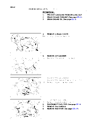
                            4.  REMOVE V-BANK COVER
                            Remove the 2 nuts and V-bank cover.


                   A23208


                            5.    REMOVE AIR CLEANER
                            (a)   Disconnect the ventilation hose No.2.


                   A23095


                            (b)   Disconnect the vacuum hose.
                            (c)   Disconnect the mass air flow meter connector.
                            (d)   Remove the 2 wire harness clamps.


                   A23209


                            (e)   Loosen the 2 hose clamps.
                            (f)   Remove the 2 bolts and air cleaner
                            6.    DISCONNECT FUEL PIPE (See page SF-1)
                            7.    REMOVE FAN SHROUD
                            8.    REMOVE RADIATOR (See page CO-17)


                   A23210
                                                                             EM-63
ENGINE MECHANICAL (1GR-FE)   -   CYLINDER HEAD

                     9.   LOOSEN FAN W/FLUID COUPLING
                     Loosen the 4 nuts of the fan w/ fluid coupling.


            A23114


                     10. REMOVE DRIVE BELT
                     Release the belt tension by turning the belt tensioner counter-
                     clockwise. Remove the V-ribbed belt from the belt tensioner.
                     11. REMOVE FAN W/FLUID COUPLING
                     12. SEPARATE VANE PUMP (See page SR-47)
                     13. REMOVE GENERATOR (See page CH-7)
                     14. SEPARATE COOLER COMPRESSOR
                          (See page AC-54)
           A22797    15. DISCONNECT HEATER WATER OUTLET AND INLET
                          HOSE


                     16.   REMOVE INTAKE AIR SURGE TANK
                     (a)   Disconnect the 2 water by-pass hoses.


           A23085


                     (b)   Disconnect the fuel vapor feed hose.


           A23086
EM-64
        ENGINE MECHANICAL (1GR-FE)   -   CYLINDER HEAD

                            (c)   Disconnect the ventilation hose.


                   A23087


                            (d)   Disconnect the 2 VSV connectors.
                            (e)   Disconnect the throttle body w/ motor connector.
                            (f)   Separate the 3 wire harness clamps and hose clamp.


                   A23088


                            (g)   Remove the 2 bolts and throttle body bracket.


                   A23089


                            (h)   Remove the bolt and oil baffle plate.
                            (i)   Remove the 4 bolts and 2 surge tank stays.


                   A23090
                                                                           EM-65
ENGINE MECHANICAL (1GR-FE)   -   CYLINDER HEAD

                    (j)   Remove the 2 nuts.
                    (k)   Using a socket hexagon wrench 8, remove the 4 bolts, in-
                          take air surge tank and gasket.
                    17.   REMOVE IGNITER (See page IG-6)


           A23091


                    18.   REMOVE CYLINDER HEAD COVER
                    (a)   Remove the 10 bolts, 3 seal washers, 2 nuts, cylinder
                          head cover RH and gasket.
                    (b)   Remove the 2 nuts, oil filter cap housing and gasket.


           A22970


                    (c)   Remove the 10 bolts, 3 seal washers, 2 nuts, cylinder
                          head cover LH and gasket.
                    19.   REMOVE INTAKE MANIFOLD
                    (a)   Disconnect the 6 fuel injector connectors.


           A23092


                    (b)   Remove the 10 bolts, intake manifold and 2 gaskets.
                    20.   REMOVE WATER BY-PASS JOINT
                    (a)   Disconnect the engine coolant temperature sensor con-
                          nector.
                    (b)   Disconnect the heater hose.


           A22882


                    (c)   Remove the 2 bolts, 4 nuts, water by-pass joint RR and
                          2 gaskets.
                    (d)   Remove the O-ring from the water outlet pipe.
                    21.   REMOVE CAMSHAFT TIMING OIL CONTROL VALVE


           A22883
EM-66
                                          ENGINE MECHANICAL (1GR-FE)             -   CYLINDER HEAD

                                                                     22. REMOVE OIL CONTROL VALVE FILTER
RH Bank                           LH Bank
                                                                     Remove the plug, filter and gasket from each cylinder head.
                                                                     23. REMOVE VVT SENSOR
                                                                     24. REMOVE RH AND LH FRONT EXHAUST PIPE
                                                                     25. REMOVE RH AND LH EXHAUST MANIFOLD
                                                                     (a) Remove the 6 bolts and 2 exhaust manifold stays.
                                                                     (b) Remove the 12 nuts, RH and LH exhaust manifold and 2
                                                                           gaskets.
                                                            A22969   26. REMOVE OIL PAN (See page EM-32)
                                                                     27. REMOVE TIMING CHAIN COVER (See page EM-32)
                                                                     28. REMOVE TIMING CHAIN (See page EM-32)
                                                                     29. REMOVE CAMSHAFT
                                                                     NOTICE:
                                                                     As the thrust clearance of the camshaft is small, the cam-
                                                                     shaft must be kept level while it is being removed. If the
                                                                     camshaft is not kept level, the portion of the cylinder head
                                                                     which receives the shaft thrust may crack or be damaged,
                                                                     causing the camshaft to seize or break. To avoid this, the
                                                                     following steps should be carried out.

RH Bank                                                              (a)   Remove the camshafts of the RH bank.
                                                                           (1) Rotate the camshafts counterclockwise using the
                                                                               wrench so that the cam lobes of the No. 1 cylinder
                                                                               face each direction as shown in the illustration.


                                                            A22886


RH Bank                                                                    (2)       Using several steps, uniformly loosen and remove
                                                                                     the 16 bearing cap bolts in the sequence as shown
                                            15         11
                3             7                                                      in the illustration.
                                                                           (3)       Remove the 8 bearing caps and 2 camshafts.
                4             8                16       12
            2             6               14
                                                        10

                1             5             13          9
                                                            A22887


 LH Bank                                                             (b)   Remove the camshafts of the LH bank.
                                                                           (1) Using several steps, uniformly loosen and remove
       11                                                                      the 16 bearing cap bolts in the sequence as shown
                    15            7                3
                                                                               in the illustration.
  12                                                                       (2) Remove the 8 bearing caps and 2 camshafts.
                     16       8                4
  10            14                    6             2                30.   REMOVE CAMSHAFT BEARING NO.1 AND NO.2


        9           13            5                1
                                                            A22910
                                                                                                          EM-67
                      ENGINE MECHANICAL (1GR-FE)    -   CYLINDER HEAD


LH Cylinder Head                           31.   REMOVE CYLINDER HEAD
                                           (a)   Using several steps, remove the 2 cylinder head bolts on
 2                                               the LH cylinder head in the sequence as shown in the il-
                                                 lustration.


1


                                  A22911


RH Cylinder Head                           (b) Using several steps, loosen the 8 cylinder head bolts on
       3      5       7       2                each cylinder head with a 10 mm bi-hexagon wrench in
                                               the sequence as shown in the illustration. Remove the 16
                                               cylinder head bolts and plate washers.
                                           NOTICE:
                                            S  Be careful not to drop the plate washers into the cylin-
                                               der head.
      1       8       6       4             S  Cylinder head warpage or cracking could result from
                                               removing the bolts in the incorrect order.

LH Cylinder Head

          1       8       6   4


          3       5       7   2
                                  A22977


                                           (c)    Lift the cylinder head from the dowels on the cylinder
                                                  block, and place the 2 cylinder heads on wooden blocks
                                                  on a bench.
                                           NOTICE:
                                           Be careful not to damage the contact surfaces of the cylin-
                                           der head and cylinder block.
                                           HINT:
                                           If the cylinder head is difficult to lift off, pry between the cylinder
                                  A22978   head and cylinder block with a screwdriver.
                                           (d) Remove the RH and LH cylinder head gaskets.
                                           32. REMOVE CYLINDER HEAD GASKET


◦ Jabse Service Manual Search 2026 ◦ Jabse PravopisonTap.bg ◦ Other service manual resources online : FixyaeServiceinfo