Service Manuals, User Guides, Schematic Diagrams or docs for : . Car Manuals Toyota Tundra 2000-2006 Approved 04-06 techinfo.toyota.com ileaf 06toyrm 06toypdf 06rmsrc 06tundra em2uzfe cylblo disa

<< Back | Home

Most service manuals and schematics are PDF files, so You will need Adobre Acrobat Reader to view : Acrobat Download Some of the files are DjVu format. Readers and resources available here : DjVu Resources
For the compressed files, most common are zip and rar. Please, extract files with Your favorite compression software ( WinZip, WinRAR ... ) before viewing. If a document has multiple parts, You should download all, before extracting.
Good luck. Repair on Your own risk. Make sure You know what You are doing.


Image preview - the first page of the document
disa


>> Download disa documenatation <<

Text preview - extract from the document
EM-100
                         ENGINE MECHANICAL (2UZ-FE)   -   CYLINDER BLOCK
                                                                                                   EM122-06


                                             DISASSEMBLY
                                             1.    INSTALL ENGINE TO ENGINE STAND
                                             2.    REMOVE TIMING BELT AND PULLEYS
                                                   (See page EM-16)
                                             3.    REMOVE CYLINDER HEAD (See page EM-36)


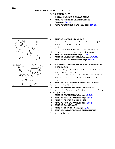
                                             4.    REMOVE WATER BYPASS PIPE
          Pull                               (a)   Disconnect the wire clamp (for knock sensor 1, 2) from
                 Wire                              bracket of the water bypass pipe.
                 Clamp                       (b)   Remove the bolt.
                                             (c)   Pull out the water bypass pipe from the water pump.
 O-Ring                                      (d)   Remove the O-ring from the water bypass pipe.
                                             5.    REMOVE STARTER (See page ST-6)
                                             6.    REMOVE KNOCK SENSORS (See page SF-70)
                                    A05112   7.    REMOVE VVT SENSORS (See page SF-79)

LH Side                                      8.  DISCONNECT ENGINE WIRE FROM LH SIDE OF CYL-
                                                 INDER BLOCK
                                             (a) Remove the 2 bolts and engine wire cover from the LH
                                                 side of the cylinder block.
                                             (b) Remove the 2 bolts, disconnect the brackets on the en-
                                                 gine wire from the cylinder block and engine mounting
                                                 bracket.
                                             9.  REMOVE OIL COOLER PIPE BRACKET FOR A/T
                                    A08472   Remove the bolt and bracket.
                                             10. REMOVE ENGINE MOUNTING BRACKETS
                                             Remove the 4 bolts and mounting bracket. Remove the 2
                                             mounting brackets.
                                             11. REMOVE WATER PUMP (See page CO-6)
                                             12. REMOVE NO.2 OIL PAN (See page LU-8)
                                             13. REMOVE OIL PAN BAFFLE PLATE
                                             14. REMOVE NO.1 OIL PAN (See page LU-8)
                                             15. REMOVE OIL STRAINER
                                             16. REMOVE OIL PUMP (See page LU-8)
                                             17. REMOVE ENGINE COOLANT DRAIN UNIONS
                                             Remove the 2 drain unions.
                                                                                  EM-101
      ENGINE MECHANICAL (2UZ-FE)   -   CYLINDER BLOCK

                          18.   REMOVE REAR OIL SEAL RETAINER
                          (a)   Remove the 7 bolts.
                          (b)   Using a screwdriver, remove the oil seal retainer by prying
                                the portion between the oil seal retainer and main bearing
                                cap.
pry                       (c)   Remove the O-ring.


                 A05086


                          19. CHECK CONNECTING ROD THRUST CLEARANCE
                          Using a dial indicator, measure the thrust clearance while mov-
                          ing the connecting rod back an forth.
                                 Standard thrust clearance:
                                 0.160 to 0.290 mm (0.0063 to 0.0114 in.)
                                 Maximum thrust clearance: 0.35 mm (0.0138 in.)
                          If the thrust clearance is greater than maximum, replace the
                          connecting rod assembly(s). If necessary, replace the crank-
                 A05100   shaft.
                                 Connecting rod thickness:
                                 22.880 to 22.920 mm (0.9008 to 0.9024 in.)


                          20.   REMOVE CONNECTING ROD CAPS AND CHECK OIL
                                CLEARANCE
                          (a)   Check the matchmarks on the connecting rod and see it
                                cap to ensure correct reassembly.
                          (b)   Remove the 2 connecting rod cap bolts.


                 A05104


                          (c)   Using the 2 removed connecting rod cap bolts, remove
                                the connecting rod cap and lower bearing by wiggling the
                                connecting rod cap right and left.
                          HINT:
                          Keep the lower bearing inserted with the connecting rod cap.
                          (d) Clean the crank pin and bearing.
                          (e) Check the crank pin and bearing for peeling and
                                 scratches.
                 A05105   If the crank pin or bearing is damaged, replace the bearings. If
                          necessary, replace the crankshaft.
EM-102
                     ENGINE MECHANICAL (2UZ-FE)   -   CYLINDER BLOCK

Plastigage                               (f)   Lay a strip of Plastigage across the crank pin.


                                A05102


                                         (g)  Install the connecting rod cap with the 2 bolts.
                                              (see page EM-118)
                                         NOTICE:
                                         Do not turn the crankshaft.
                                         (h) Remove the 2 bolts, connecting rod cap and lower bear-
                                              ing. (See procedure (b) and (c) above)


                                A05101


                                         (i)    Measure the Plastigage at its widest point.
                                                Standard oil clearance:
                                                0.021 to 0.047 mm (0.0008 to 0.0019 in.)
                                                Maximum oil clearance: 0.059 mm (0.0023 in.)
                                         If the oil clearance is greater than maximum, replace the bear-
                                         ings. If necessary, replace the crankshaft.


                                A05103


                                         HINT:
                                         If using a standard bearing, replace it with one having the same
                                         number. If the number of the bearing cannot be determined, se-
                                         lect the correct bearing by adding together the numbers im-
    Number
    Mark                                 printed on the connecting rod cap and crankshaft, then select-
                                         ing the bearing with the same number as the total. There are 6
              No.4                       sizes of standard bearings, marked "2", "3", "4", "5", "6" and "7".
             No.3
  No.1                                                                             Number mark
      No.2                                Connecting rod cap 1    1        2   1   2   3   2   3   4   3 4   4
                                          Crankshaft         1    2        1   3   2   1   3   2   1   3 2   3
                      Number              Use bearing        2         3           4           5        6    7
                      Mark                EXAMPLE:
         Number                           Connecting rod cap "3" + Crankshaft "1"
         Mark                             = Total number 4 (Use bearing "4")


A05852
A05087
A05853                          A05175
                                                                                                                    EM-103
                        ENGINE MECHANICAL (2UZ-FE)      -   CYLINDER BLOCK

                                                      Reference
                                                      Connecting rod big end inside diameter:
                                                    Mark "1"            55.000 to 55.006 mm (2.1654 to 2.1656 in.)
                                                    Mark "2"            55.006 to 55.012 mm (2.1656 to 2.1658 in.)
                                                    Mark "3"            55.012 to 55.018 mm (2.1658 to 2.1661 in.)
                                                    Mark "4"            55.018 to 55.024 mm (2.1661 to 2.1663 in.)
                                                      Crankshaft crank pin diameter:
                                                    Mark "1"            51.994 to 52.000 mm (2.0470 to 2.0472 in.)
                                                    Mark "2"            51.988 to 51.994 mm (2.0468 to 2.0470 in.)
                                                    Mark "3"            51.982 to 51.988 mm (2.0465 to 2.0468 in.)

                                                      Standard sized bearing center wall thickness:
                                                    Mark "2"             1.487 to 1.490 mm (0.0585 to 0.0587 in.)
                                                    Mark "3"             1.490 to 1.493 mm (0.0587 to 0.0588 in.)
                                                    Mark "4"             1.493 to 1.496 mm (0.0588 to 0.0589 in.)
                                                    Mark "5"             1.496 to 1.499 mm (0.0589 to 0.0590 in.)
                                                    Mark "6"             1.499 to 1.502 mm (0.0590 to 0.0591 in.)
                                                    Mark "7"             1.502 to 1.505 mm (0.0591 to 0.0593 in.)
                                              (j)     Completely remove the Plastigage.
                                              21.     REMOVE PISTON AND CONNECTING ROD AS-
                                                      SEMBLIES
                                              (a)     Using a ridge reamer, remove all the carbon from the top
                                                      of the cylinder.
                                              (b)     Push the piston, connecting rod assembly and upper
                                                      bearing through the top of the cylinder block.
                                              HINT:
                        Ridge                 S     Keep the bearings, connecting rod and cap together.
                        Reamer       A04852   S     Arrange the piston and connecting rod assemblies in cor-
                                                    rect order.
                                              22. CHECK CRANKSHAFT THRUST CLEARANCE
                                              Using a dial indicator, measure the thrust clearance while prying
                                              the crankshaft back and forth with a screwdriver.
                                                    Standard thrust clearance:
                                                    0.020 to 0.220 mm (0.0008 to 0.0087 in.)
                                                    Maximum thrust clearance: 0.30 mm (0.0118 in.)
                                              If the thrust clearance is greater than maximum, replace the
                                              thrust washers as a set.
                                     A05096         Thrust washer thickness:
                                                    2.440 to 2.490 mm (0.0961 to 0.0980 in.)
                                              23. REMOVE MAIN BEARING CAPS AND CHECK OIL
                           3
                    7                               CLEARANCE
            9                                 (a) Uniformly loosen and remove the 10 main bearing cap
    5
1                                     4             bolts in several passes, in the sequence shown.
                                 8
                         10
                6
        2

                                     A05095
EM-104
              ENGINE MECHANICAL (2UZ-FE)   -   CYLINDER BLOCK

                                  (b)    Using 2 screwdrivers, pry out the main bearing cap, and
                                         remove the 5 main bearing caps, 5 lower bearings and 2
                                         lower thrust washers (No.3 main bearing cap only).
                                  NOTICE:
                                  Be careful not to damage the cylinder block.
                                  HINT:
                                   S     Keep the lower bearing and main bearing cap together.
                                   S     Arrange the main bearing caps and lower thrust washers
                         A05093          in correct order.
                                  (c) Lift out the crankshaft.
                                  HINT:
                                  Keep the upper bearings and upper thrust washers together
                                  with the cylinder block.
                                  (d) Clean each main journal and bearing.
                                  (e) Check each main journal and bearing for peelings and
                                         scratches.
                                  If the journal or bearing is damaged, replace the bearings. If
                                  necessary, replace the crankshaft.


 Plastigage                       (f)   Place the crankshaft on the cylinder block.
                                  (g)   Lay a strip of Plastigage across each journal.


                         A05097


                                  (h) Install the main bearing caps. (See page EM-118)
                                  NOTICE:
                                  Do not turn the crankshaft.
                                  (i)  Remove the main bearing caps.
                                       (See procedure (a) and (b) above)


                         A05095


                                  (j)    Measure the Plastigage at its widest point.
                                         Standard clearance:
                                         No.1, No.5
                                         0.028 to 0.046 mm (0.0011 to 0.0018 in.)
                                         Others
                                         0.040 to 0.058 mm (0.0016 to 0.0023 in.)
                                         Maximum clearance: 0.065 mm (0.0026 in.)
                                  If the oil clearance is greater than maximum, replace the bear-
                         A05098   ings. If necessary, replace the crankshaft.
                                                                                                             EM-105
                       ENGINE MECHANICAL (2UZ-FE)      -   CYLINDER BLOCK


         No.3   No.4 No.5                     HINT:
                                              If using a standard bearing, replace it with one having the same
                            Number Mark
                                              number. If the number of the bearing cannot be determined, se-
                             No.2             lect the correct bearing by adding together the numbers im-
                            No.1
                                              printed on the cylinder block and crankshaft, then refer to the
                               Number         table below for the appropriate bearing number. There are 5
                               Mark           sizes of the standard bearings. For No.1 and No.5 position
                                              bearings, use bearings marked "3", "4", "5", "6" and "7". For oth-
                                              ers position bearings, use bearings marked "1", "2", "3", "4" and
                                              "5".
                                     No.5       No.1, No.5
                      No.2                                                   Mark               Use bearing
                     No.1                                                    0 to 5                  3
                                                  Cylinder block (A)         6 to 11                 4
                              No.3 No.4                  +                  12 to 17                 5
                                                   Crankshaft (B)           18 to 23                 6
                            Number                                          24 to 28                 7
                            Mark               EXAMPLE:
A05089                                         Cylinder block "08" + Crankshaft "06"
A05088
A05090                               A05176    = Total number 14 (Use bearing "5")


                                                Others
                                                                             Mark               Use bearing
                                                                             0 to 5                  1
                                                  Cylinder block (A)         6 to 11                 2
                                                         +                  12 to 17                 3
                                                   Crankshaft (B)           18 to 23                 4
                                                                            24 to 28                     5
                                               EXAMPLE:
                                               Cylinder block "08" + Crankshaft "06"
                                               = Total number 14 (Use bearing "3")

                                                    Reference
                                                    Cylinder block main journal bore diameter (A):
                                                   Mark "00"                    72.000 mm (2.8346 in.)
                                                   Mark "01"                    72.001 mm (2.8347 in.)
                                                   Mark "02"                    72.002 mm (2.8347 in.)
                                                   Mark "03"                    72.003 mm (2.8348 in.)
                                                   Mark "04"                    72.004 mm (2.8348 in.)
                                                   Mark "05"                    72.005 mm (2.8348 in.)
                                                   Mark "06"                    72.006 mm (2.8349 in.)
                                                   Mark "07"                    72.007 mm (2.8349 in.)
                                                   Mark "08"                    72.008 mm (2.8350 in.)
                                                   Mark "09"                    72.009 mm (2.8350 in.)
                                                   Mark "10"                    72.010 mm (2.8350 in.)
                                                   Mark "11"                    72.011 mm (2.8351 in.)
                                                   Mark "12"                    72.012 mm (2.8351 in.)
                                                   Mark "13"                    72.013 mm (2.8352 in.)
                                                   Mark "14"                    72.014 mm (2.8352 in.)
EM-106
         ENGINE MECHANICAL (2UZ-FE)    -   CYLINDER BLOCK


                                   Mark "15"                    72.015 mm (2.8352 in.)
                                   Mark "16"                    72.016 mm (2.8353 in.)
                                   Crankshaft main journal diameter (B):
                                   Mark "00"                    67.000 mm (2.6378 in.)
                                   Mark "01"                    66.999 mm (2.6378 in.)
                                   Mark "02"                    66.998 mm (2.6377 in.)
                                   Mark "03"                    66.997 mm (2.6377 in.)
                                   Mark "04"                    66.996 mm (2.6376 in.)
                                   Mark "05"                    66.995 mm (2.6376 in.)
                                   Mark "06"                    66.994 mm (2.6376 in.)
                                   Mark "07"                    66.993 mm (2.6375 in.)
                                   Mark "08"                    66.992 mm (2.6375 in.)
                                   Mark "09"                    66.991 mm (2.6374 in.)
                                   Mark "10"                    66.990 mm (2.6374 in.)
                                   Mark "11"                    66.989 mm (2.6374 in.)
                                   Mark "12"                    66.988 mm (2.6373 in.)
                                   Standard bearing center wall thickness:
                                   No.1 and No.5
                                   Mark "3"             2.487 to 2.490 mm (0.0979 - 0.0980 in.)
                                   Mark "4"             2.490 to 2.493 mm (0.0980 - 0.0981 in.)
                                   Mark "5"             2.493 to 2.496 mm (0.0981 - 0.0983 in.)
                                   Mark "6"             2.496 to 2.499 mm (0.0983 - 0.0984 in.)
                                   Mark "7"             2.499 to 2.502 mm (0.0984 - 0.0985 in.)
                                   Others
                                   Mark "1"             2.481 to 2.484 mm (0.0977 - 0.0978 in.)
                                   Mark "2"             2.484 to 2.487 mm (0.0978 - 0.0979 in.)
                                   Mark "3"             2.487 to 2.490 mm (0.0979 - 0.0980 in.)
                                   Mark "4"             2.490 to 2.493 mm (0.0980 - 0.0981 in.)
                                   Mark "5"             2.493 to 2.496 mm (0.0981 - 0.0983 in.)
                             (k)   Completely remove the Plastigage.
                             24.   REMOVE CRANKSHAFT
                             (a)   Lift up the crankshaft.
                             (b)   Remove the 5 upper main bearings and 2 upper thrust
                                   washers from the cylinder block.
                             HINT:
                             Arrange the main bearing caps, bearings and thrust washers in
                             correct order.
                             25. CHECK FIT BETWEEN PISTON AND PISTON PIN
                             Try to move the piston back and forth on the piston pin.
                             If any movement is felt, replace the piston and pin as a set.


                    A04862
                                                                            EM-107
ENGINE MECHANICAL (2UZ-FE)    -   CYLINDER BLOCK

                    26.     REMOVE PISTON RINGS
                    (a)     Using a piston ring expander, remove the 2 compression
                            rings.
                    (b)     Remove the 2 side rails and oil ring by hand.
                    HINT:
                    Arrange the piston rings in correct order only.


           A04873


                    27.     DISCONNECT CONNECTING ROD FROM PISTON
                    (a)     Using a small screwdriver, pry out the 2 snap rings.


           A04860


                    (b)     Gradually heat the piston to approx. 60


◦ Jabse Service Manual Search 2026 ◦ Jabse PravopisonTap.bg ◦ Other service manual resources online : FixyaeServiceinfo